<?xml version="1.0" encoding="utf-8"?><feed xmlns="http://www.w3.org/2005/Atom" ><generator uri="https://jekyllrb.com/" version="4.4.1">Jekyll</generator><link href="https://log.thewildbramble.com/feed.xml" rel="self" type="application/atom+xml" /><link href="https://log.thewildbramble.com/" rel="alternate" type="text/html" /><updated>2025-04-05T20:29:48+00:00</updated><id>https://log.thewildbramble.com/feed.xml</id><title type="html">clone. remix. push.</title><subtitle>A build log.</subtitle><author><name>TheWildBramble</name></author><entry><title type="html">Headphones hotswap box</title><link href="https://log.thewildbramble.com/headphones-hotswap/" rel="alternate" type="text/html" title="Headphones hotswap box" /><published>2025-04-04T05:10:00+00:00</published><updated>2025-04-04T05:10:00+00:00</updated><id>https://log.thewildbramble.com/headphones-hotswap</id><content type="html" xml:base="https://log.thewildbramble.com/headphones-hotswap/"><![CDATA[<p>I needed a way to switch my TRRS headphones between my desktop and laptop without digging around for cables. Built a little box for it.</p>

<p><img src="/assets/img/headphones-hotswap/hotswap-3a.jpg" width="301" height="300" />
<img src="/assets/img/headphones-hotswap/hotswap-3b.jpg" width="300" height="300" /></p>

<p>Three TRRS jacks: one for input (the headphones), two for outputs (laptop and desktop). Signal gets routed through a 4P3T rotary switch — one position for each output, and a center-off position for mute/disconnect. Nice to have a hardware kill-switch in the middle.</p>

<p>Used shielded TRRS jacks and wired straight through, no components. Added copper shielding tape to the inside of the enclosure to keep noise out — it helped. The box is aluminium, pocket-sized, with a knurled knob on top. Labelled with a paint pen.</p>

<p>No popping, no weird interference, and I can swap sources without pulling cables. Feels nice to have a physical switch instead of relying on software or dongles. I just have to route 2 TRRS cables, one to the laptop and one to the desktop.</p>

<p><img src="/assets/img/headphones-hotswap/hotswap-2a.jpg" width="295" height="300" />
<img src="/assets/img/headphones-hotswap/hotswap-2b.jpg" width="300" height="300" />
<img src="/assets/img/headphones-hotswap/hotswap-2c.jpg" width="300" height="300" /></p>

<h2 id="shopping-list">Shopping list</h2>

<ul>
  <li>3x <strong>TRRS 3.5mm jack sockets</strong>: <a href="https://www.digikey.se/en/products/detail/same-sky-formerly-cui-devices/SJ1-43502PM/5130707">here</a>.</li>
  <li>a 4p3t <strong>potentiometer</strong> <a href="https://www.digikey.se/en/products/detail/e-switch/KC43A30-001NLS/101809">here</a>. Having 3 positions, 1 is for each output, and one is disconnected</li>
  <li>some *adhesive** copper tape, like <a href="https://www.amazon.se/s?k=copper+tape&amp;crid=2N5NUYPE9OGTM&amp;sprefix=copper+tape%2Caps%2C91&amp;ref=nb_sb_noss_1">this</a>.</li>
  <li>a <strong>knob</strong> like <a href="https://www.digikey.se/en/products/detail/apem-inc/420065A14/1797575">this</a>.</li>
  <li>some M2, M3, or self-tapping screws</li>
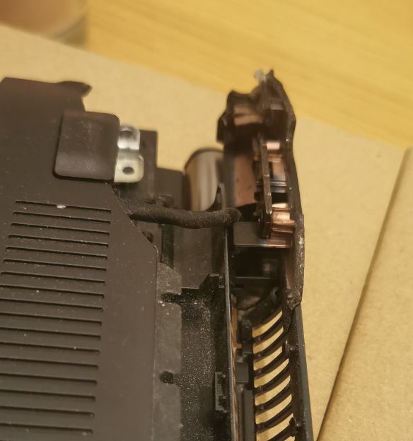
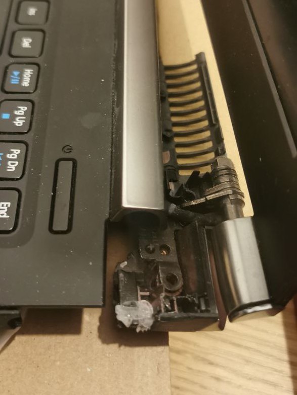
</ul>]]></content><author><name>TheWildBramble</name></author><category term="DIY" /><category term="3d Printing" /><category term="Workspace" /><summary type="html"><![CDATA[Headphone Hotswap Box]]></summary></entry><entry><title type="html">DIY rack-mounted laptop</title><link href="https://log.thewildbramble.com/diy-rack-mounted-laptop/" rel="alternate" type="text/html" title="DIY rack-mounted laptop" /><published>2023-11-25T11:00:00+00:00</published><updated>2023-11-25T11:00:00+00:00</updated><id>https://log.thewildbramble.com/diy-rack-mounted-laptop</id><content type="html" xml:base="https://log.thewildbramble.com/diy-rack-mounted-laptop/"><![CDATA[<p>Do you have any old hardware lying around your house? I certainly do. I have an old VN7 gaming laptop that suffered a serious drop a few years back, and it was immediately replaced by a smaller, lighter machine.</p>

<p>The damage was in a critical spot where both the power supply and the monitor connected. As a result, it didn’t take long for it to completely fall apart after the drop:</p>

<p><img src="/assets/img/diy-server-rack/broken-laptop-1.jpg" width="281" height="300" />
<img src="/assets/img/diy-server-rack/broken-laptop-2.jpg" width="226" height="300" /></p>

<p>However, this laptop had pretty decent specs for its time, so it seemed like a waste to just let it gather dust.</p>

<p>I already run a <a href="/nas-case-for-nanopi-m4/#software">home assistant instance</a> that manages also additional Docker applications. Recently, I found myself in need of a slightly more powerful machine to use as a development server. The timing couldn’t have been more perfect!</p>

<p>I soon discovered that server hardware is prohibitively expensive. A 1U chassis ranges from 50 to 100 EUR, which is quite costly, especially considering the additional modifications needed, like drilling extra ventilation holes. Plus, I already had some spare rack parts at home, so I decided to build one myself instead!</p>

<h2 id="shopping-list">Shopping list</h2>

<ul>
  <li>an <strong>angled C5 power cable</strong> for the laptop’s power supply: <a href="https://www.amazon.se/dp/B0C3HJYWLL">here</a>. Being angled saves some useful space.</li>
  <li>an <strong>angled USB micro cable</strong> to connect the monitor display <a href="https://www.amazon.se/dp/B07B4YW2SH">here</a>. Being angled saves some useful space.</li>
  <li>a <strong>momentary switch</strong> like <a href="https://www.electrokit.com/en/product/push-switch-1-p-off-on-vandal-proof-led-blue/">this</a>.</li>
  <li>a <strong>status led</strong> like <a href="https://www.electrokit.com/en/product/led-5mm-green-with-resistor-for-5v/">this</a> with its <a href="https://www.electrokit.com/en/product/led-socket-convex-top-5-mm/">holder</a>.</li>
  <li>an <strong>arduino-compatible board</strong>, plus some headers and cables. I used an old Arduino Micro, which I had lying around. Any board will do, as long as it supports serial communication via USB.</li>
  <li>a tiny <strong>OLED screen</strong>, like <a href="https://www.amazon.se/-/en/Fasizi-Serial-128x64-Display-Arduino/dp/B09Z2D5GBW/">this</a>.</li>
  <li><strong>2020</strong> or <strong>2040 aluminium profiles</strong> work magic. I used two <a href="https://www.electrokit.com/en/product/v-slot-2040-natural-anodized-250mm/">2040</a> 250mm and one <a href="https://www.electrokit.com/en/product/v-slot-2020-natural-anodized-500mm/">2020</a> 500mm which I cut to size.</li>
  <li>a few <strong>corner brackets</strong>. Either <a href="https://www.electrokit.com/en/product/cast-90-degree-corner-bracket-for-2020-natural/">external ones</a>, or <a href="https://www.electrokit.com/en/product/inside-hidden-corner-bracket-for-2020/">hidden ones</a>.</li>
  <li>a bunch of <strong>machine screws</strong>. Those can be found in various lengths <a href="">here</a>, I used mostly M3 and M5 screws in 8, 10 and 16mm lengths. And a bunch of T-nuts, like <a href="https://www.electrokit.com/en/product/t-nut-drop-in-for-2020-m5-single/">these</a> or <a href="https://www.electrokit.com/en/product/t-nut-square-for-2020-m5-single/">these</a>.</li>
  <li>a bunch of <strong>threaded nuts</strong> like <a href="https://www.electrokit.com/en/product/ganginsats-m3-x-4mm-50-pack/">those</a>.</li>
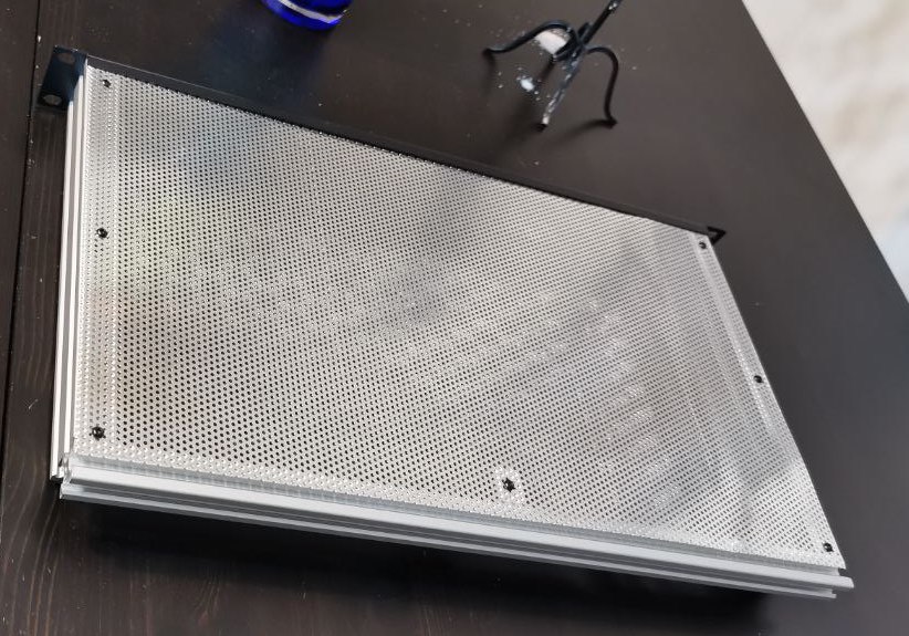
  <li>a couple of <strong>metal, wood or acrylic panels</strong>. I used <a href="https://www.amazon.se/dp/B008H19IOI">one of these</a> on one side, and a sheet of transparent acrylic I had laying around. I’ve chosen the ones made of perforated aluminium because of a few perks: it’s almost of the right size, the perforation adds ventilation for free and makes it easier to cut at home.</li>
</ul>

<h2 id="tools">Tools</h2>

<ul>
  <li>drill</li>
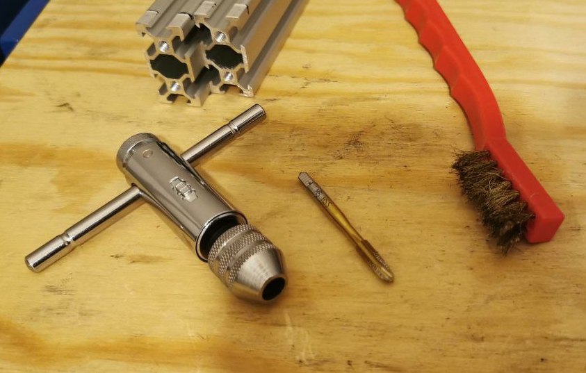
  <li>tapping tool. If you know what that is, you may already own one. If not, it’s required to tap for M5 screw into the 2020/2040 profiles, and here’s <a href="https://www.amazon.se/dp/B07V31LX96">a cheap one</a> which could last for a couple of uses :-D (I’d suggest you get a proper one, or at least one with a longer handle).</li>
  <li>files and something to cut metal, to cut a hole in the blank panel for the monitor.</li>
  <li>3d printer</li>
</ul>

<h2 id="planning-and-tests">Planning and tests</h2>

<p>The primary function of this machine will be to serve as a development server, which means I’ll mostly access it remotely from another computer. Additionally, it will operate various other software programs, and I want to be able to monitor the machine’s status easily.</p>

<p>I plan to achieve this through two methods:</p>

<ul>
  <li>Transmitting its metrics to Home Assistant using MQTT.</li>
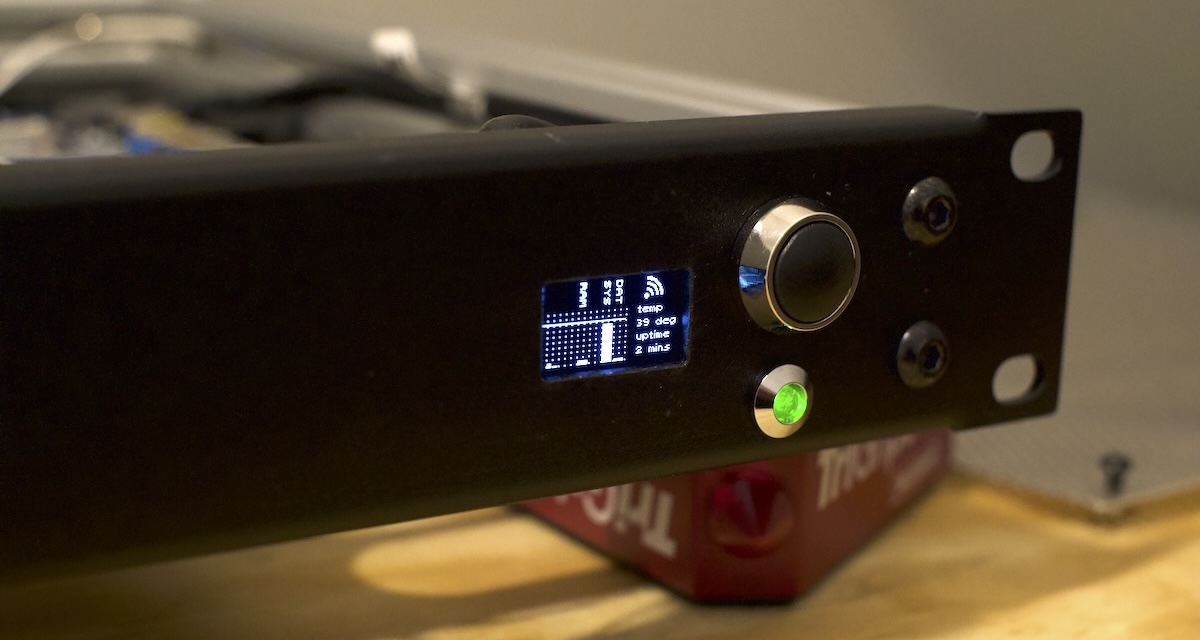
  <li>Utilizing a visible, physical status monitor to quickly assess the machine’s health at a glance.</li>
</ul>

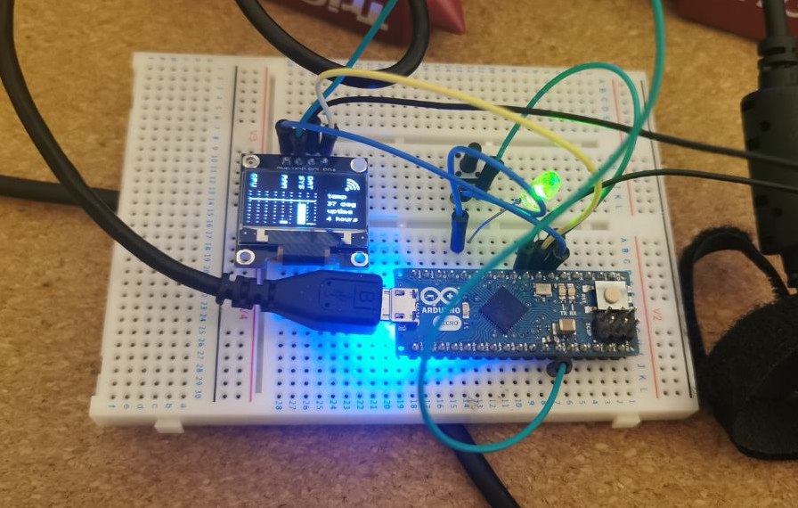
<p>Before beginning to construct the parts, I needed to verify if the monitor setup was feasible. Therefore, I decided to add some wires and give it a try.</p>

<p><img src="/assets/img/diy-server-rack/monitor-test.jpg" width="472" height="300" /></p>

<p>How does it work?</p>

<p>A Python script performs checks on:</p>

<ul>
  <li>Disk space</li>
  <li>CPU temperature</li>
  <li>Available memory</li>
  <li>Network status</li>
</ul>

<p>This script then sends that information to the Arduino board through the serial channel.
It also connects to a MQTT server which runs on Home Assistant to send it metrics about the machine.</p>

<p>The script runs as a service, starting at server boot, and is maintained actively.</p>

<p>The code on the Arduino board executes several tasks:</p>
<ul>
  <li>It receives status information via the serial channel.</li>
  <li>It plots metrics onto a grid.</li>
  <li>It displays icons based on the network status.</li>
  <li>After 10 seconds of idleness, it shows a waiting page, useful if the system goes down or disconnects.</li>
  <li>It controls an LED, turning it on or off depending on whether the host machine is transmitting data.</li>
</ul>

<p>I might write a separate post about this in the future, as there are numerous interesting details involved.</p>

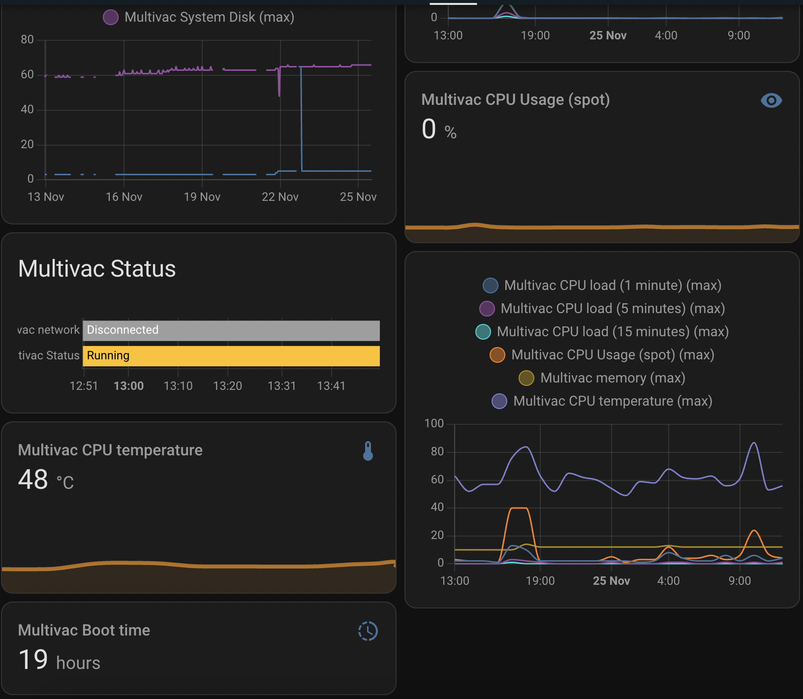
<p>Once connected to MQTT, I can display metrics about it in Home Assistant:</p>

<p><img src="/assets/img/diy-server-rack/rack-ha-status.jpg" width="500" height="435" /></p>

<p>Great! Now, software works, time to build a chassis for it!</p>

<h2 id="building-the-chassis">Building the chassis</h2>

<p>The chassis is constructed by combining aluminum profiles into a sturdy frame, which will be enclosed by one metal and one acrylic panel. 3D-printed parts will close the back and secure the disk, motherboard, and power supply in place.</p>

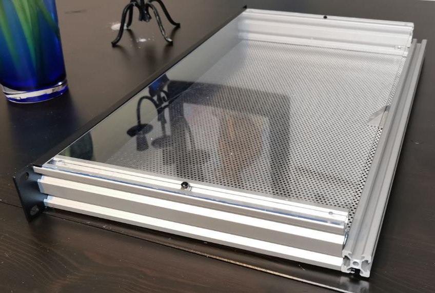
<p>To try out whether the assembly was rigid enough, I assembled the two 2020, 2040 cut to size and the panel together with a few corner brackets and screws. This requires tapping the central hole of the 250mm profiles and drilling four holes in the 19” rack panel.</p>

<p><img src="/assets/img/diy-server-rack/tapping-tools.jpg" width="471" height="300" /></p>

<p>Regrettably, I forgot to take pictures of the entire process.</p>

<p>After drilling a few holes and cutting the two panels to size, here’s a preliminary look at the chassis:
<img src="/assets/img/diy-server-rack/rack-draft-1.jpg" width="446" height="300" />
<img src="/assets/img/diy-server-rack/rack-draft-2.jpg" width="429" height="300" /></p>

<p>Now, it was time to design some plastic parts.</p>

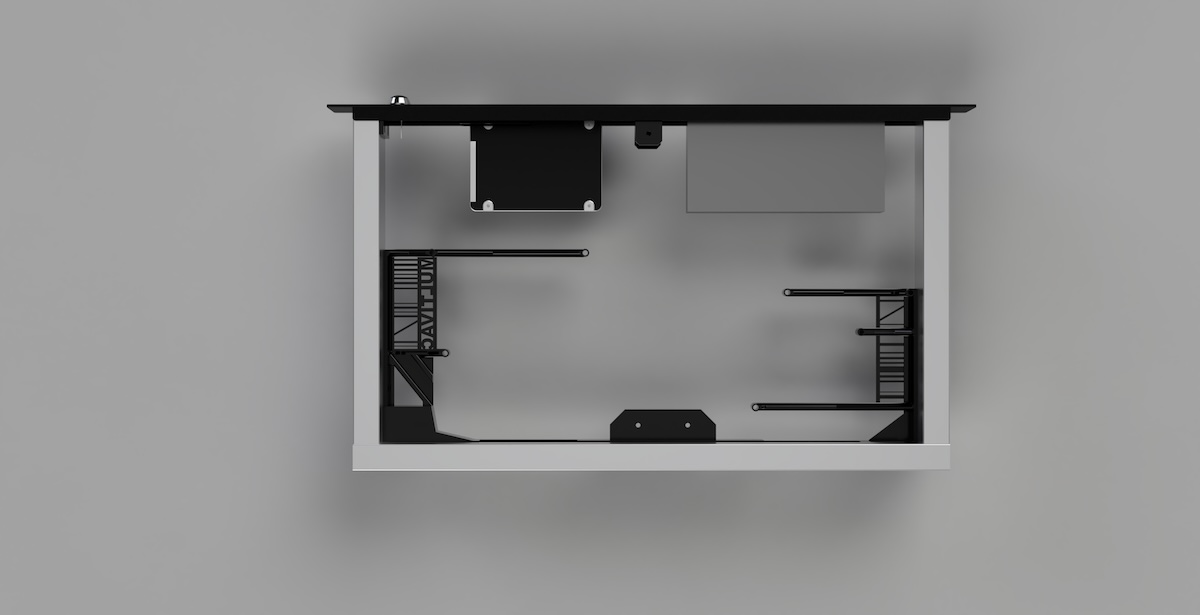
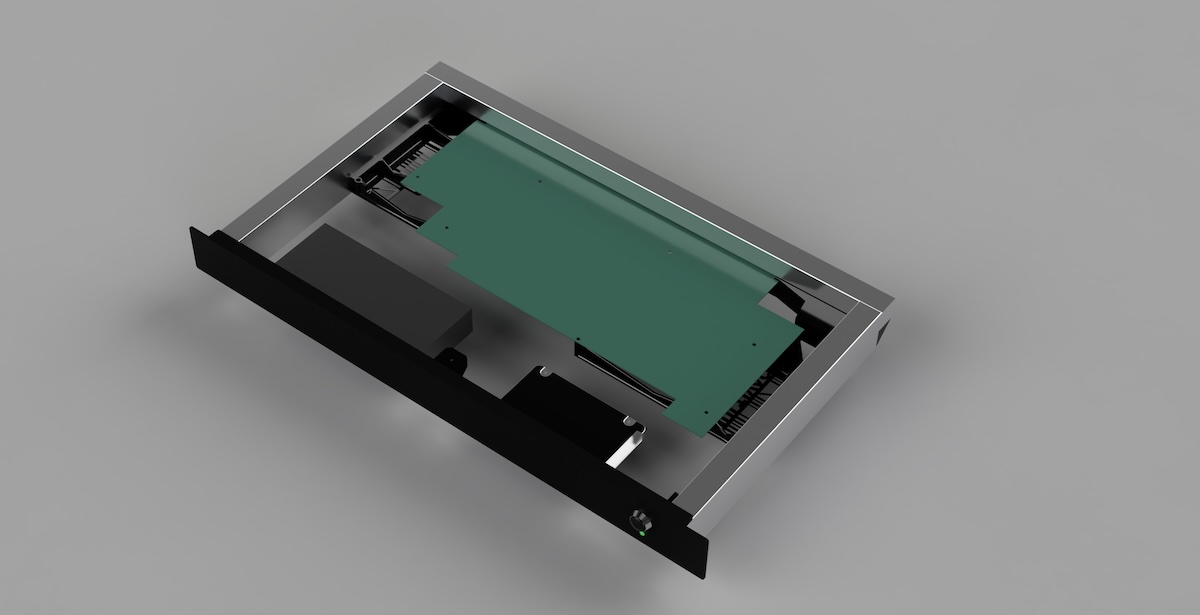
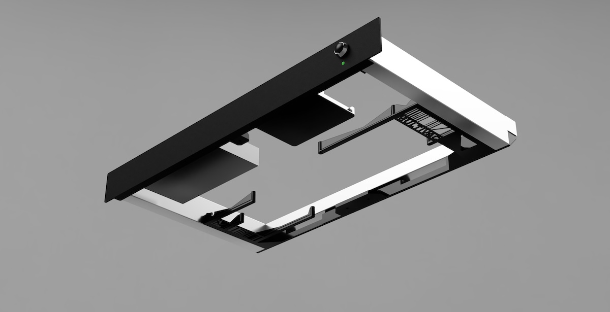
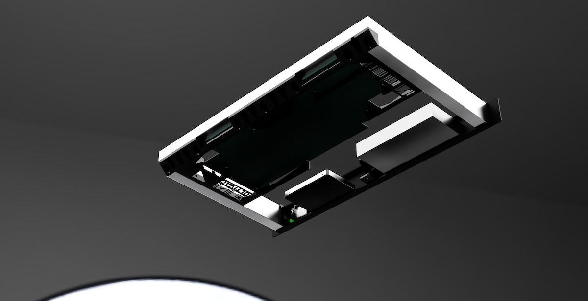
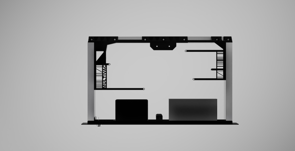
<p>For this, I traced the laptop motherboard’s outline onto paper. I measured the dimensions of both the chassis and the motherboard, then began drafting a design in Fusion 360. After a few iterations, the final render looked like this:</p>

<p><img src="/assets/img/diy-server-rack/rack-render-5.jpeg" width="800" height="410" />
<img src="/assets/img/diy-server-rack/rack-render-2.jpeg" width="400" height="205" />
<img src="/assets/img/diy-server-rack/rack-render-1.jpeg" width="400" height="205" />
<img src="/assets/img/diy-server-rack/rack-render-3.jpeg" width="400" height="205" />
<img src="/assets/img/diy-server-rack/rack-render-4.jpeg" width="400" height="205" /></p>

<h2 id="final-assembly">Final assembly</h2>

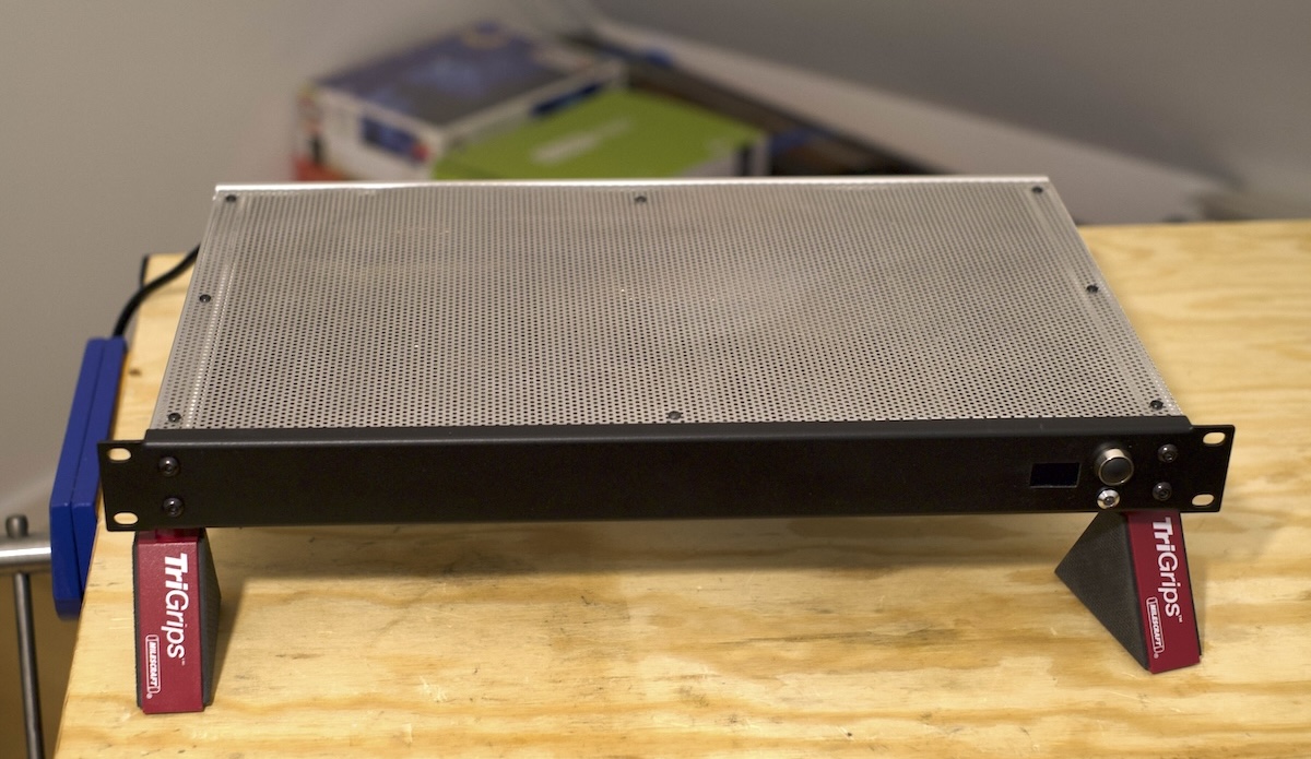
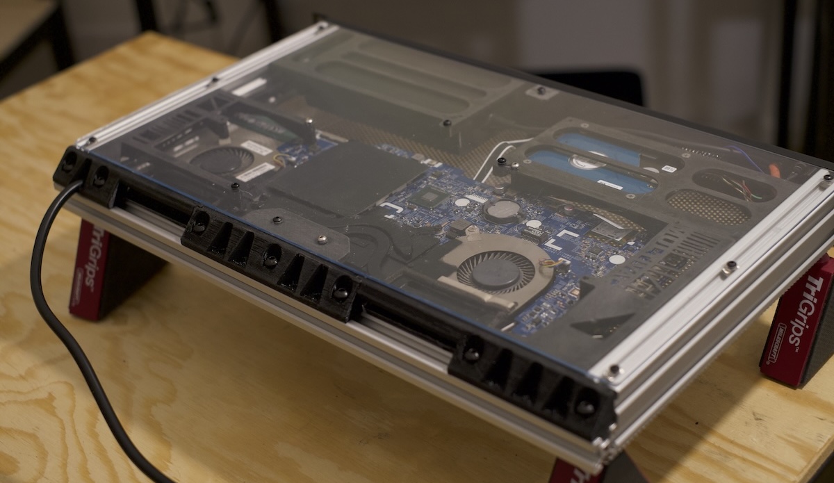
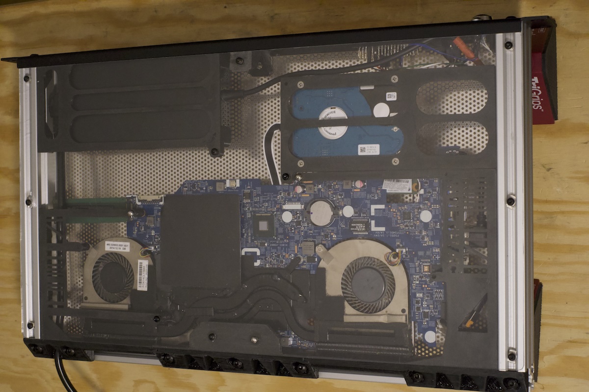
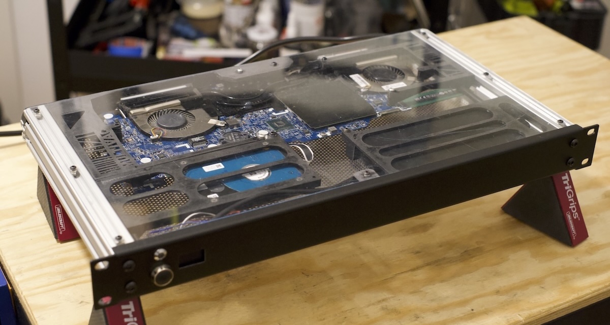
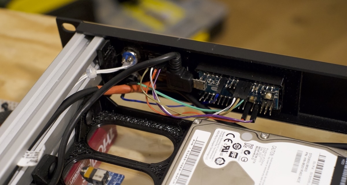
<p>Here’s the final result with everything assembled and securely bolted: looks neat, doesn’t it?</p>

<p><img src="/assets/img/diy-server-rack/rack-1.jpeg" width="400" height="232" />
<img src="/assets/img/diy-server-rack/rack-2.jpeg" width="400" height="232" />
<img src="/assets/img/diy-server-rack/rack-3.jpeg" width="400" height="267" /></p>

<p><img src="/assets/img/diy-server-rack/rack-4.jpeg" width="400" height="213" />
<img src="/assets/img/diy-server-rack/rack-5.jpeg" width="400" height="213" />
<img src="/assets/img/diy-server-rack/rack-6.jpeg" width="400" height="213" />
<img src="/assets/img/diy-server-rack/rack-7.jpeg" width="400" height="213" /></p>]]></content><author><name>TheWildBramble</name></author><category term="DIY" /><category term="3d Printing" /><category term="Server" /><category term="Arduino" /><summary type="html"><![CDATA[Upcycling an old laptop into a home server.]]></summary></entry><entry><title type="html">New NAS, new case - Odroid N2+</title><link href="https://log.thewildbramble.com/odroid-n2+-kksb-case/" rel="alternate" type="text/html" title="New NAS, new case - Odroid N2+" /><published>2023-07-01T16:00:00+00:00</published><updated>2023-07-01T16:00:00+00:00</updated><id>https://log.thewildbramble.com/odroid-n2+-kksb-case</id><content type="html" xml:base="https://log.thewildbramble.com/odroid-n2+-kksb-case/"><![CDATA[<p>While transferring the Nanoni M4, something apparently went wrong, and the board just <em>died</em>. 
I suspect it was a voltage regulator issue, but I didn’t want to scour the board for some SMD component.</p>

<p>Also, considering the numerous software compatibility issues this board caused (with <a href="/nas-case-for-nanopi-m4/#software">this one</a> being the main problem), I finally decided to replace it with something more reliable.</p>

<p>I had my eye on the <a href="https://en.odroid.se/products/odroid-n2-plus-n2-med-4gbyte-ram">Odroid N2</a> for a few years. Last time, I chose the Nanopi M4 mostly due to availability - there was a shortage of Odroids at the time. Additionally, its price was significantly higher than a Raspberry Pi. However, the recent shortage and surging prices of Raspberry Pis made purchasing an Odroid almost a bargain this time! 😄</p>

<p>Moreover, I found a sleek and impressive case that sweetened the deal:</p>

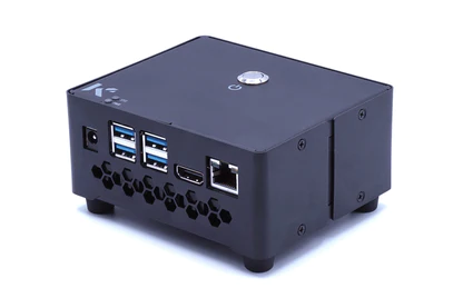
<p><img src="/assets/img/odroid/kksb-case.png" width="416" height="277" /></p>

<p>You can find it <a href="https://kksb-cases.com/products/kksb-odroid-n2-case-black">here</a>. It’s an all-metal case with a fan, a button, and status LEDs. Plus, it provides access to all the features offered by the board.</p>

<p>Having discarded the Nanopi, it’s time to hop onto an Odroid!</p>

<p>The board isn’t extremely powerful in terms of specs (it struggles a bit when I add some web servers), but it’s more than sufficient to host Home Assistant with <a href="https://phoscon.de/en/conbee2">ConBee II adapter</a>.</p>]]></content><author><name>TheWildBramble</name></author><category term="NAS" /><category term="Development boards" /><summary type="html"><![CDATA[Old Nanopi M4 NAS did not survice petty surgery.]]></summary></entry><entry><title type="html">A case for a Nanopi M4 NAS</title><link href="https://log.thewildbramble.com/nas-case-for-nanopi-m4/" rel="alternate" type="text/html" title="A case for a Nanopi M4 NAS" /><published>2023-01-14T16:00:00+00:00</published><updated>2023-01-14T16:00:00+00:00</updated><id>https://log.thewildbramble.com/nas-case-for-nanopi-m4</id><content type="html" xml:base="https://log.thewildbramble.com/nas-case-for-nanopi-m4/"><![CDATA[<p>I realized it could be nice to show some more context of where my <a href="/nas-pci-slots/">previous design</a> comes from.</p>

<p>Deciding to mount it on a PC case was actually only the last phase of a fun design journey which left me some learnings (and more spare parts then I have wished).</p>

<p>This project begins a few years back when I was looking for a better way to backup my personal data and my pictures.
I’m not going to spend much time on the solutions I’d found at the time, since most of them would probably be outdated anyway.
Instead, I’ll show some of the steps I took into designing the case for it since it’s the most fun part to me anyway.</p>

<h2 id="hardware-choices">Hardware choices</h2>
<p>My plan was to host:</p>
<ul>
  <li>a media server</li>
  <li>a home automation system</li>
  <li>a retro-game hub</li>
  <li>a file-sharing server</li>
</ul>

<p>So I was looking for a Raspberry Pi 4 alternative or a x86 board which would have had the following specs:</p>
<ul>
  <li>some kind of fast BUS to attach multiple SATA discs to it</li>
  <li>some kind of video output</li>
  <li>a small footprint</li>
</ul>

<p>Apparently none of the boards available to me at the time seemed to have any decent combination of those to my likings.</p>

<p>After a bit of research, I decided to go for a <strong>FriendlyElec <a href="https://www.friendlyelec.com/index.php?route=product/product&amp;product_id=234">NanoPi M4</a></strong>, a RK3399 SoC based ARM board. It has the same form of factor as the RPi B3+ and has ports and interfaces compatible with RPi B3+ too.</p>

<p>The board exposes HDMI output and the standard LAN + 4 USB3 configuration. It has 2 external antennas for Wifi &amp; Bluetooth.</p>

<p>I added then a <a href="https://www.friendlyelec.com/index.php?route=product/product&amp;product_id=235&amp;search=m4&amp;description=true&amp;category_id=0&amp;sub_category=true">heat sink</a>, an additional 16GB <a href="https://www.friendlyelec.com/index.php?route=product/product&amp;product_id=240&amp;search=emmc&amp;description=true&amp;category_id=0&amp;sub_category=true">eMMC 5.1 Module</a> for quicker booting and and RTC battery. On the storage side, FriendlyElec’s <a href="https://www.friendlyelec.com/index.php?route=product/product&amp;product_id=254&amp;search=m4&amp;description=true&amp;category_id=0&amp;sub_category=true">SATA HAT</a> provided 4 SATA connections directly hooked in the PCIe bus, and 12V power supply input.
I threw a Meanwell LRS-50-12 power supply on top and I was set. 
I just needed a case.</p>

<h2 id="studies">Studies</h2>

<h3 id="earlier-versions">Earlier versions</h3>

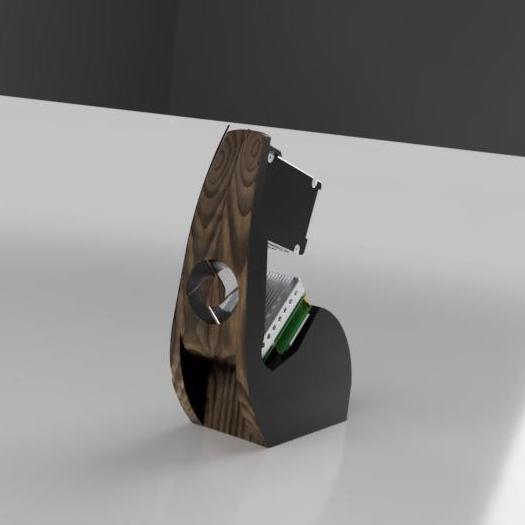
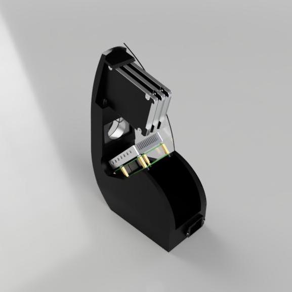
<p>The first versions of the design were focuses on having a vertical case, sporting a hybrid choice of materials and a n open frame, which can be seen in these early renders:</p>

<p><img src="/assets/img/nas-nanopi-m4/nas-m4-study-a1.jpg" width="228" height="228" />
<img src="/assets/img/nas-nanopi-m4/nas-m4-study-a2.jpg" width="228" height="228" />
<img src="/assets/img/nas-nanopi-m4/nas-m4-study-b1.jpg" width="228" height="228" />
<img src="/assets/img/nas-nanopi-m4/nas-m4-study-b2.jpg" width="228" height="228" /></p>

<p><em>Version A and version B, slightly more slanted, using a mix of aluminium, plastic and laminated wood.</em></p>

<p>Note the presence of the fan (in different dimensions). This was required as the heatsink itself had the tendency to keep the average temperature too high for my taste, so it was introduced as default requirement.</p>

<p>As fancy as they could have been, they had some major issues. A lot of refinement and finishing was due to be made due to the presence of different material and especially in the open version, cable management and air/dust flow wasn’t entirely thought through.</p>

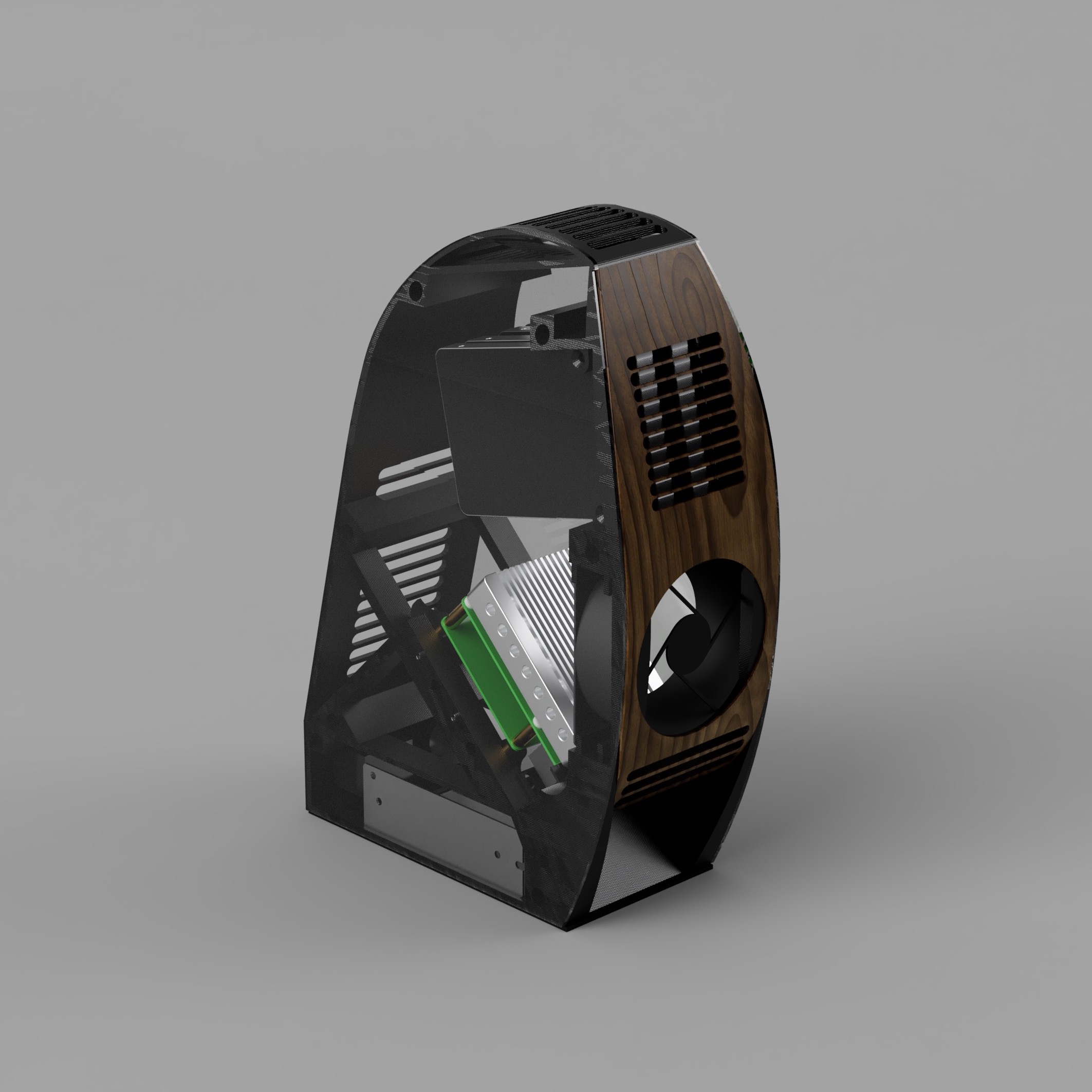
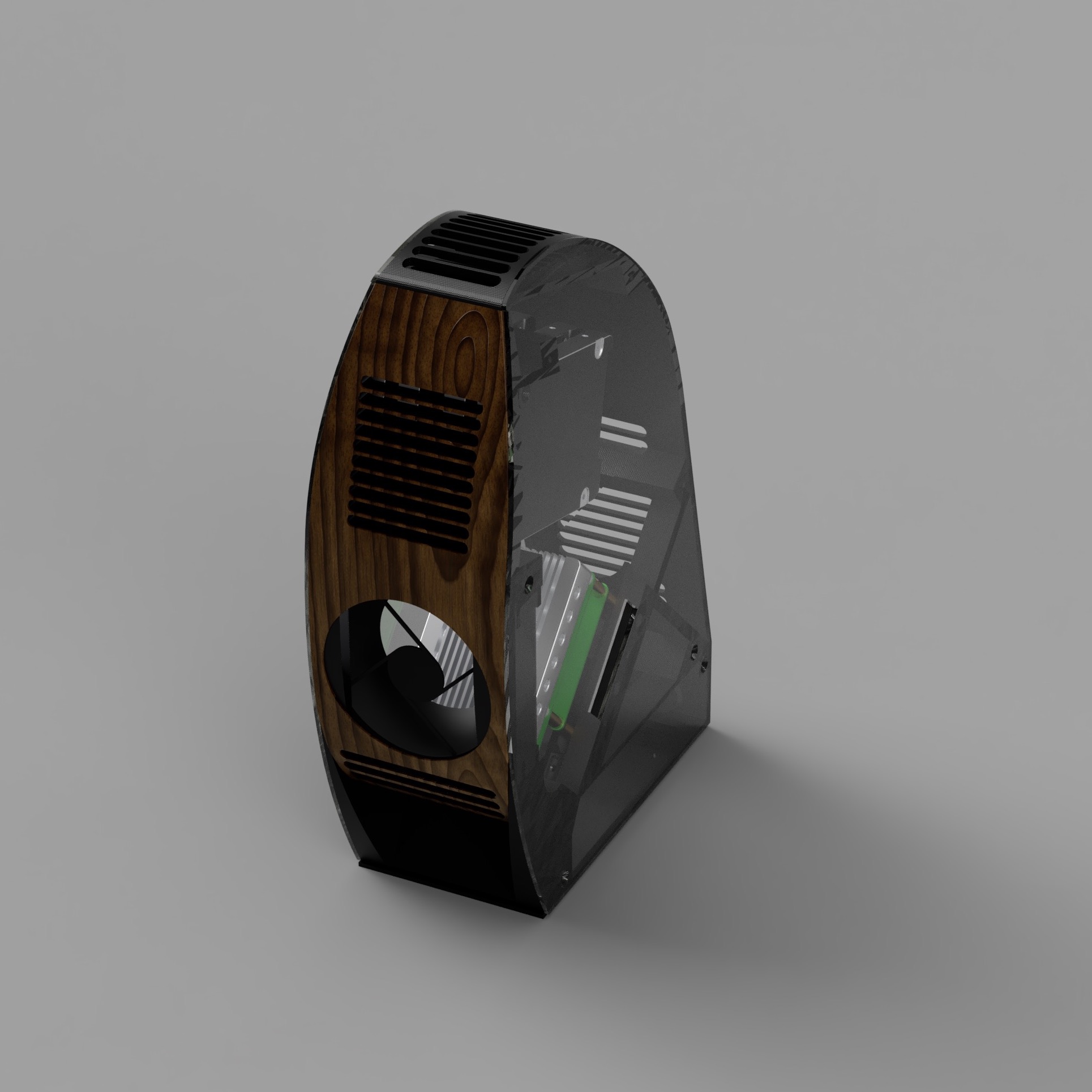
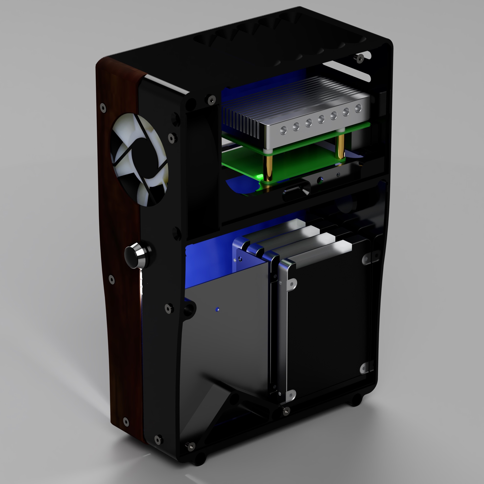
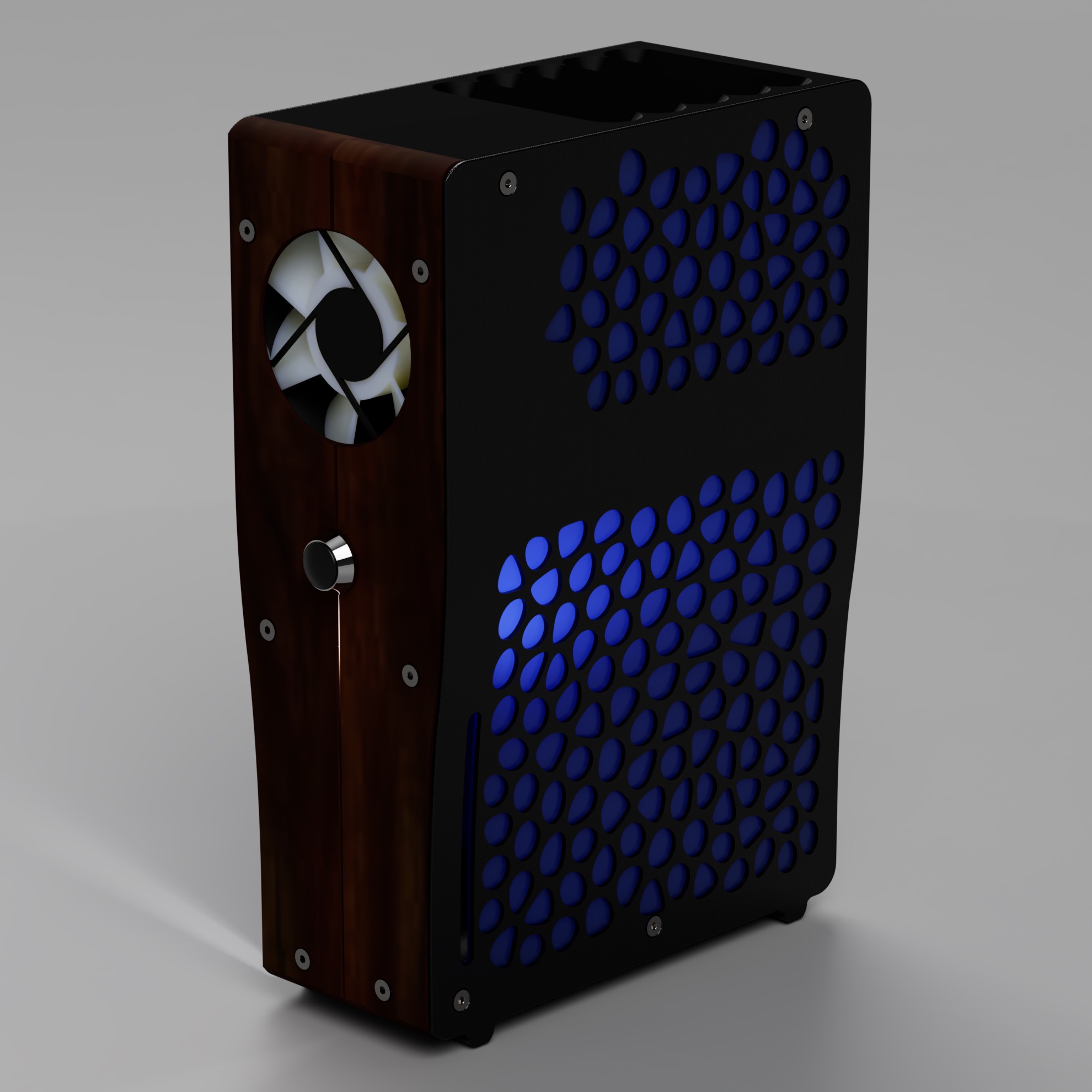
<p>A subsequential version shows a full enclosed case with a better air flow and weight management:</p>

<p><img src="/assets/img/nas-nanopi-m4/nas-m4-study-c1.jpg" width="300" height="300" />
<img src="/assets/img/nas-nanopi-m4/nas-m4-study-c2.jpg" width="300" height="300" /></p>

<p><em>Version C, fully enclosed and ready to be 3D printed.</em></p>

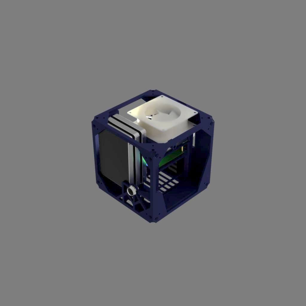
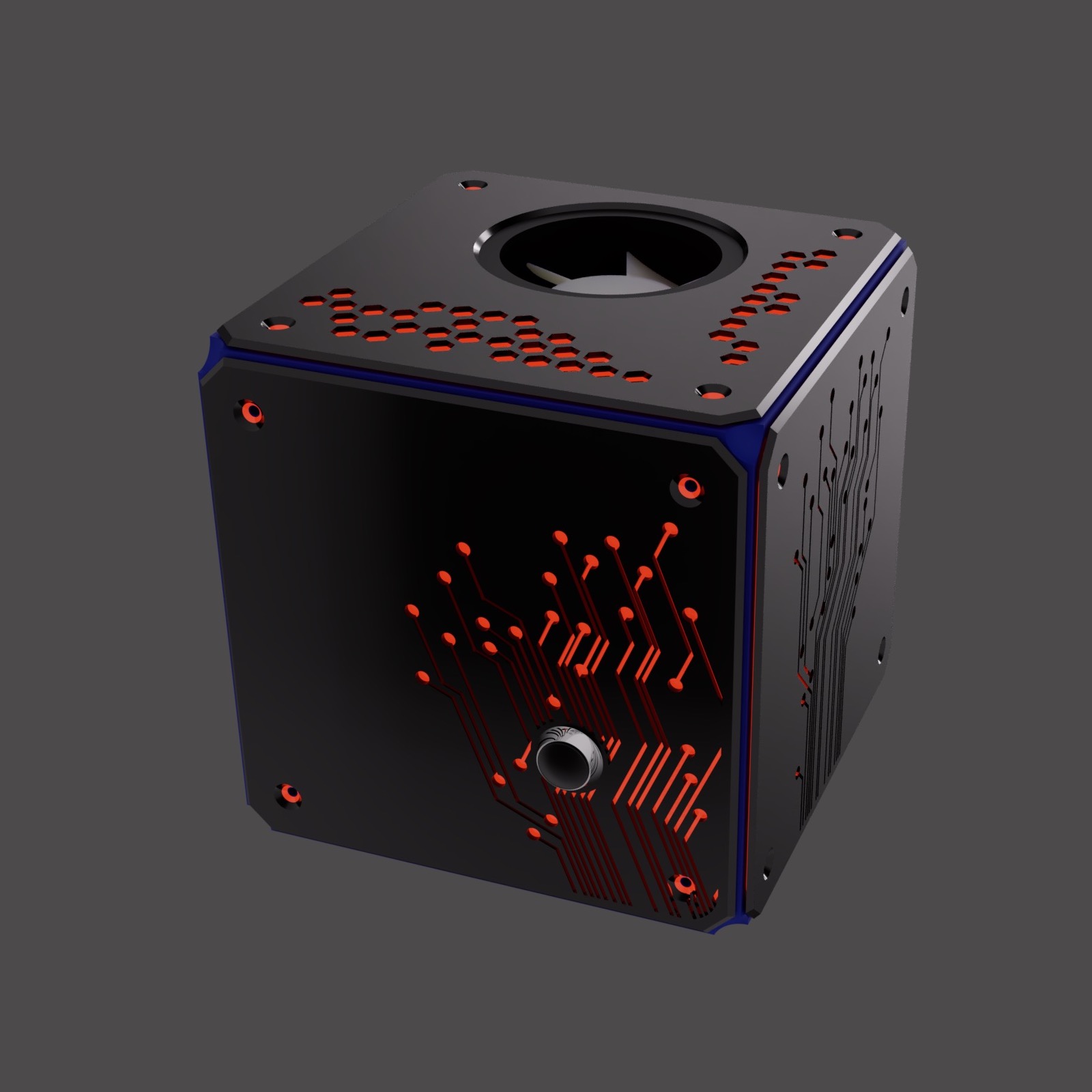
<p>Also, it showed a first draft of the transparent/light theme which will come back in the next version. This version had however some size constraints that made hard for me to be printed on my 3D printer, so this too was discarded.</p>

<p>So the first three designs (though in my opinion more elegant than the one I got to prototype later on) never got to be printed.</p>

<h3 id="a-flat-cube">A flat cube</h3>

<p>The next iteration went in a completely different direction. Rather than having a vertical case (Xbox style!) to lie near the TV bench, I decided to try design a version which could <em>actually be printed on my 3D printer</em> and double its form as a decorative item.</p>

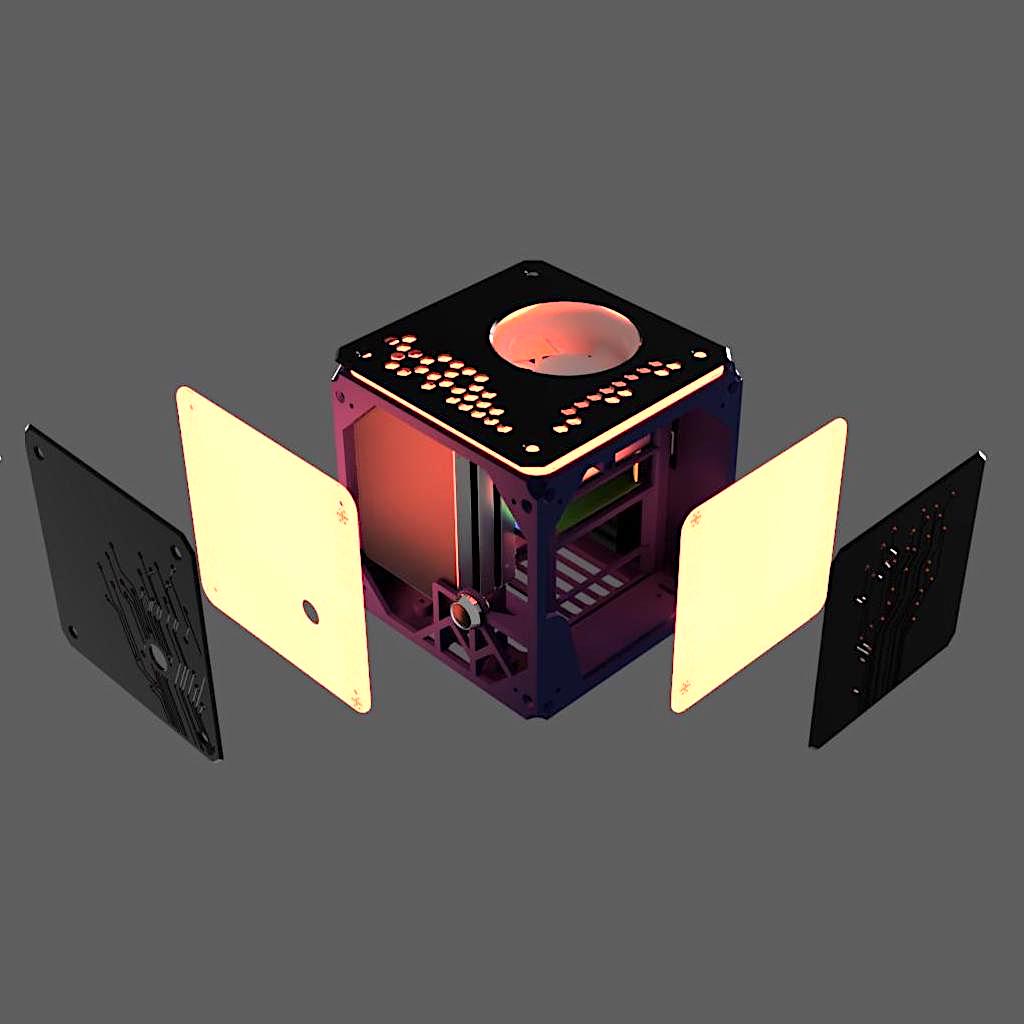
<p>Picking up on the transparent theme from the previuos iteration, I made so it could have some sort of ‘night lamp’ effect and serve also as a decorative object on my desk.</p>

<p>It features a ‘flat’ design which can be printed easily in pieces and screwed together to form a cube. 
Several layers are put on top of each other to filter the light in different shapes.</p>

<ul>
  <li>On the inside, a thick structure holds the development board onto the back of the machine, where all the plugs are firmly connected.</li>
  <li>Outside there’s a frame layer, made in matt PLA. It serves as a base and it’s screwed into a solid cubic structure.</li>
  <li>Then, a thin, red, translucent PLA which purpose is just to ‘colour’ the lights from the development board.</li>
  <li>Then a fully opaque, dark grey layer inlayed with ‘electronic’ flavoured decorations, constitutes the ‘skin’ of the case.</li>
</ul>

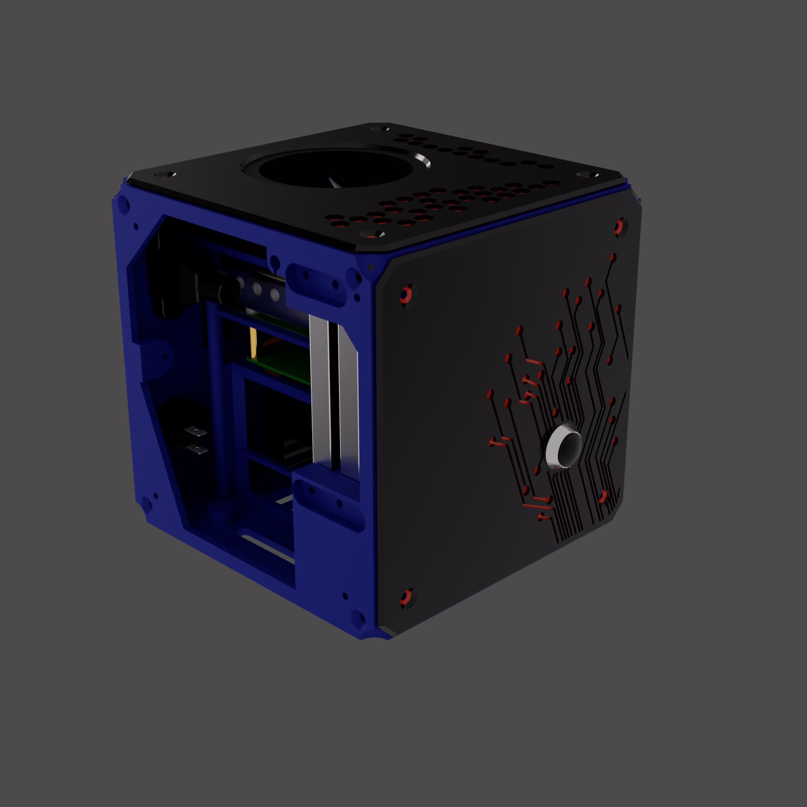
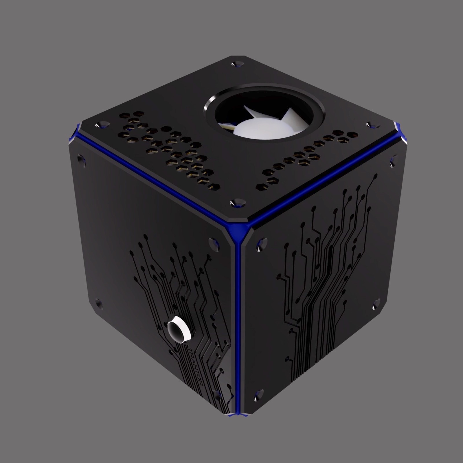
<p>Here’s how it rendered on planning phase:</p>

<p><img src="/assets/img/nas-nanopi-m4/nas-m4-study-d2.jpg" width="305" height="305" />
<img src="/assets/img/nas-nanopi-m4/nas-m4-study-d3.jpg" width="305" height="305" />
<img src="/assets/img/nas-nanopi-m4/nas-m4-study-d8.jpg" width="305" height="305" /></p>

<p><img src="/assets/img/nas-nanopi-m4/nas-m4-study-d6.jpg" width="460" height="460" />
<img src="/assets/img/nas-nanopi-m4/nas-m4-study-d7.jpg" width="460" height="460" /></p>

<p><img src="/assets/img/nas-nanopi-m4/nas-m4-d1.jpg" width="300" height="300" />
<img src="/assets/img/nas-nanopi-m4/nas-m4-d2.jpg" width="300" height="300" />
<img src="/assets/img/nas-nanopi-m4/nas-m4-d5.jpg" width="305" height="305" /></p>

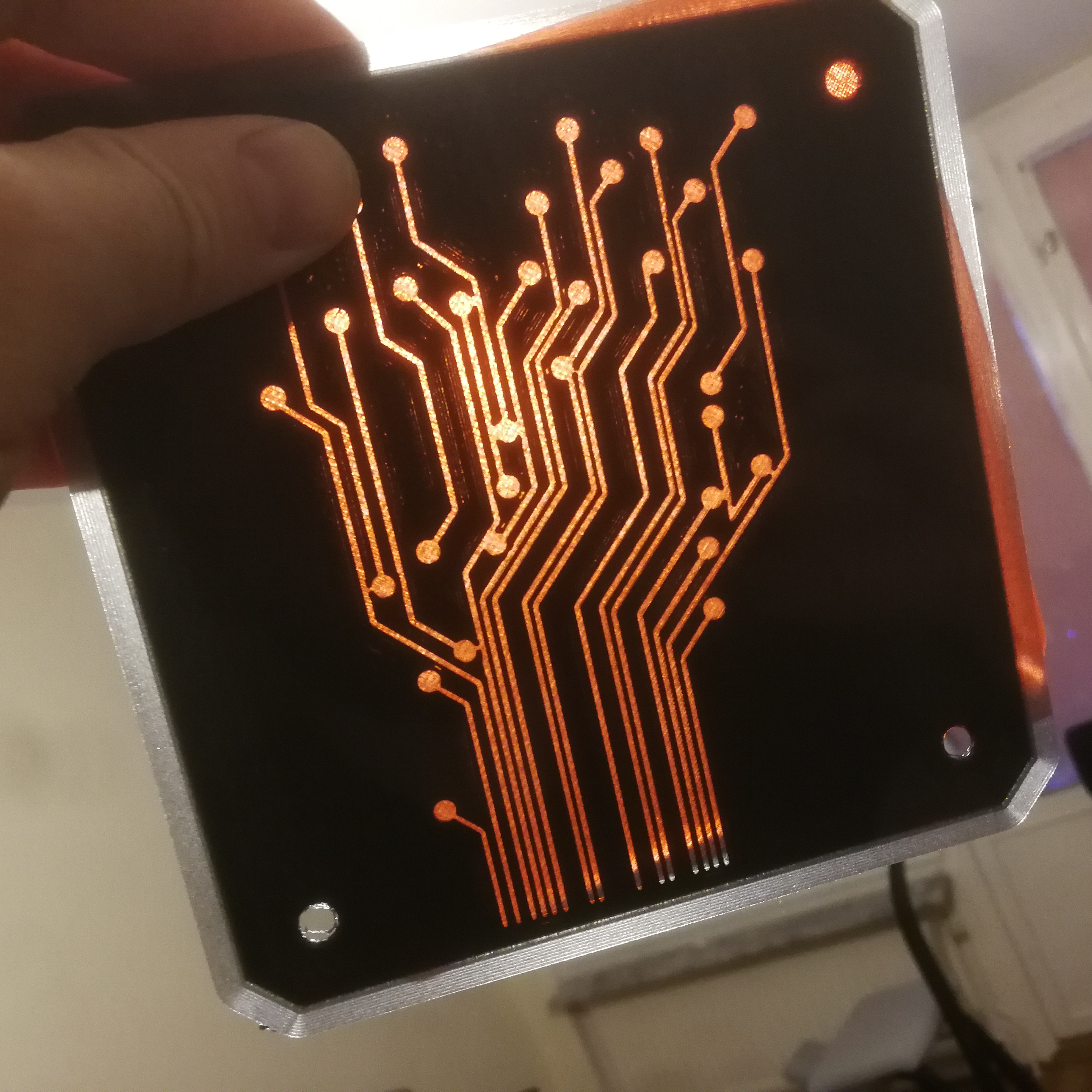
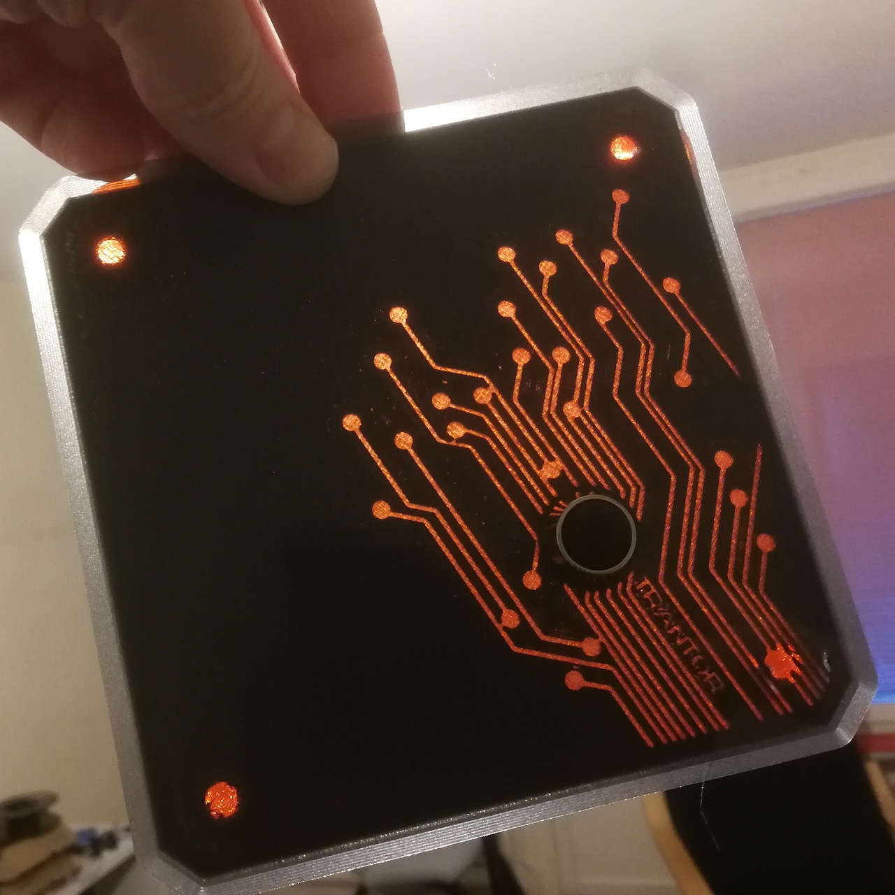
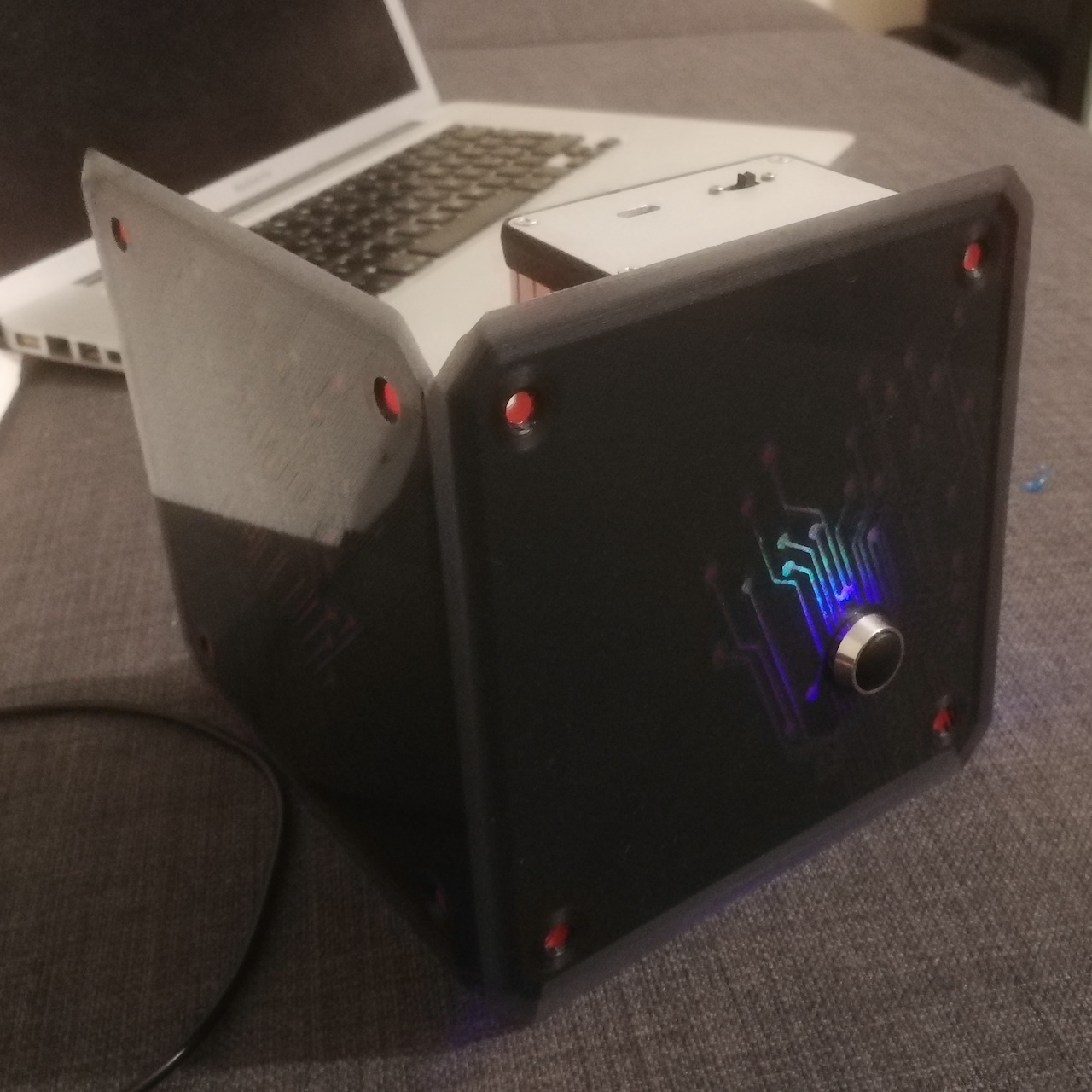
<p>And in reality:</p>

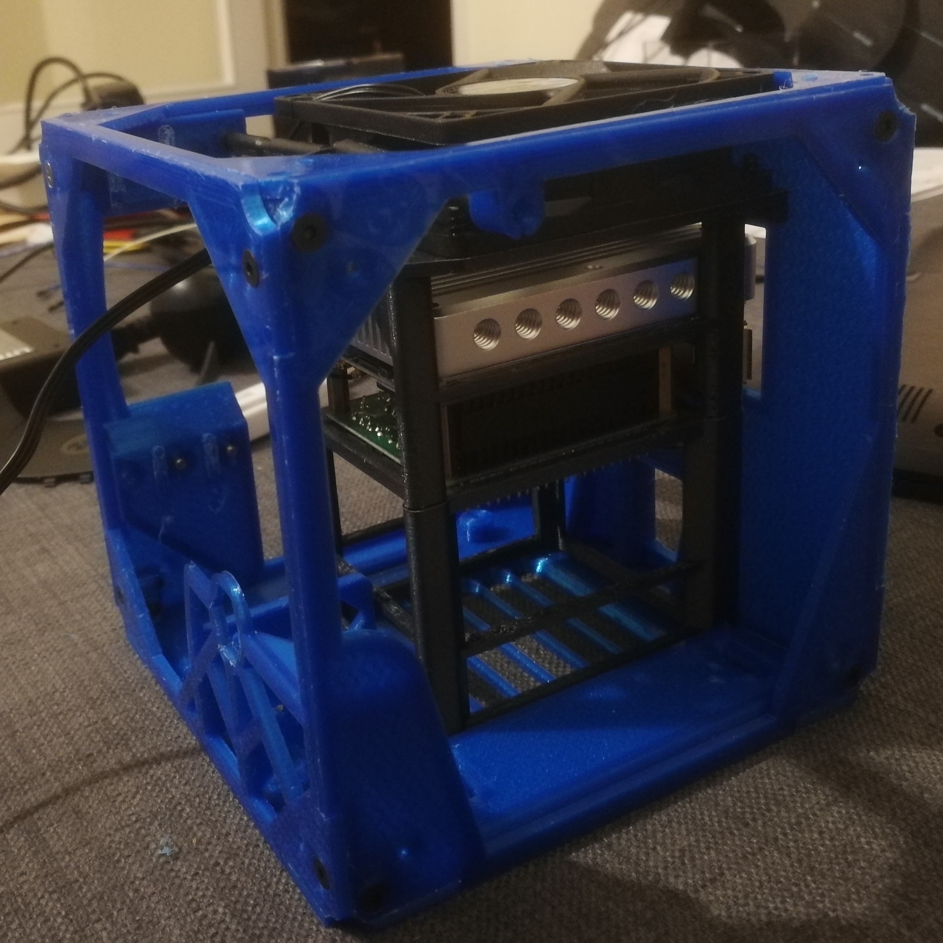
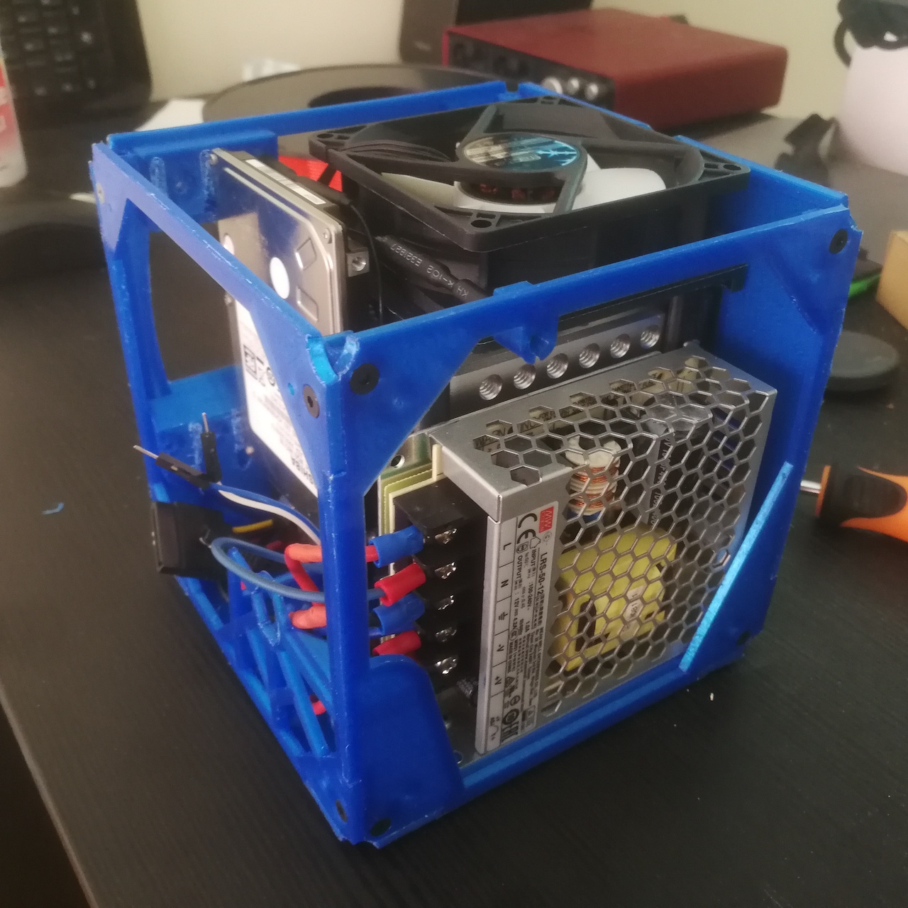
<p><img src="/assets/img/nas-nanopi-m4/nas-m4-d3.jpg" width="305" height="305" />
<img src="/assets/img/nas-nanopi-m4/nas-m4-d4.jpg" width="305" height="305" /></p>

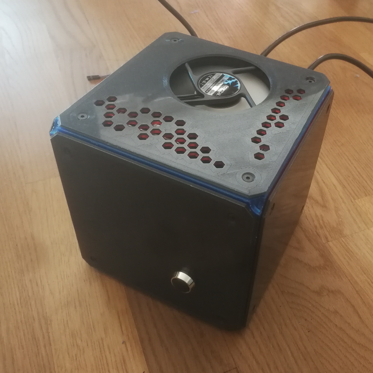
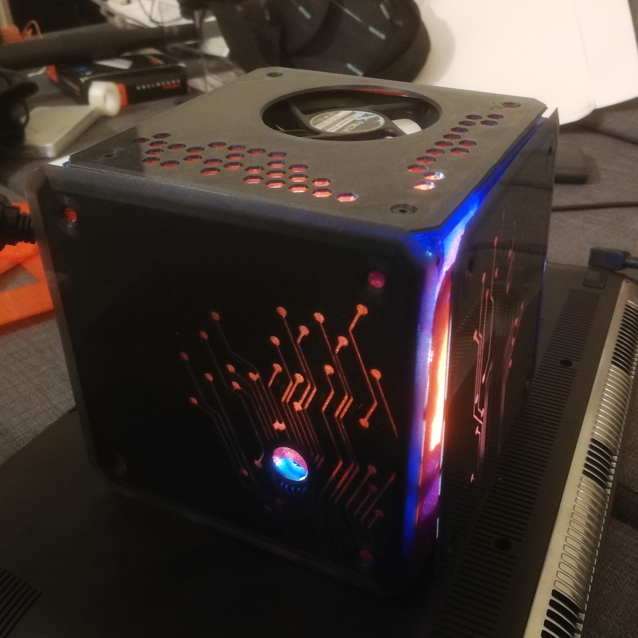
<p><img src="/assets/img/nas-nanopi-m4/nas-m4-d6.jpg" width="460" height="460" />
<img src="/assets/img/nas-nanopi-m4/nas-m4-d7.jpg" width="460" height="460" /></p>

<p>The results were as expected. Powered from 250V AC, and width a side of arund 150mm, it was a nice light spot to on my living room for a while.</p>

<h2 id="aftermath">Aftermath</h2>
<p>The NAS worked for a couple years without any issues. 
At some point, I decided to migrate my files back to a cloud provider. I didn’t have a case for having a NAS anymore.
And since I don’t even have any need for the SATA hat, the case actually had run without disks for quite a while.
Ultimately, the fan started to get noisy, or I guess the original requirements changed a bit, or I just gotten tired of seeing this chunky cubic, half empty machine on my desk.
Eventually, I decided that it wasn’t worth having a machine all day in plain sight with a less than silent fan, and I decided to downsize the project even more.</p>

<p>At the time of writing, the M4 runs on the secluded intimacy of my main PC’s case. <a href="/nas-pci-slots/">Check it out</a>.</p>

<h2 id="software">Software</h2>
<p>This part is controversial. After a bit of trial an error, the Steamlink app not being supported (sigh, it’s not a RaspberryPi) and having I migrated all my files to other cloud providers with much better luck…. the original plans much changed after a couple of years.
So I’d given up to having some of the functions I was looking for in the first place (:-D) and finalized on a rather simple setup.</p>

<p>Now the ‘NAS’ is more of a home automation system running on pumped up development board.
The board now hosts just Armbian with dockerized versions of Home Assistant, a service supporting the <a href="https://phoscon.de/en/conbee2">ConBee II adapter</a> to which I connect all my Zigbee devices, and that’s it.</p>]]></content><author><name>TheWildBramble</name></author><category term="DIY" /><category term="3d Modelling" /><category term="3d Printing" /><category term="NAS" /><category term="Development boards" /><summary type="html"><![CDATA[Designing and printing a case for a Nanopi M4 NAS]]></summary></entry><entry><title type="html">NAS mounted on a PCI Slot</title><link href="https://log.thewildbramble.com/nas-pci-slots/" rel="alternate" type="text/html" title="NAS mounted on a PCI Slot" /><published>2023-01-11T18:00:00+00:00</published><updated>2023-01-11T18:00:00+00:00</updated><id>https://log.thewildbramble.com/nas-pci-slots</id><content type="html" xml:base="https://log.thewildbramble.com/nas-pci-slots/"><![CDATA[<p>The FriendlyElec <a href="https://www.friendlyelec.com/index.php?route=product/product&amp;product_id=234">NanoPi M4</a> is a RK3399 SoC based ARM board. It has the same form of factor as the RPi B3+ and has ports and interfaces compatible with RPi B3+ too.</p>

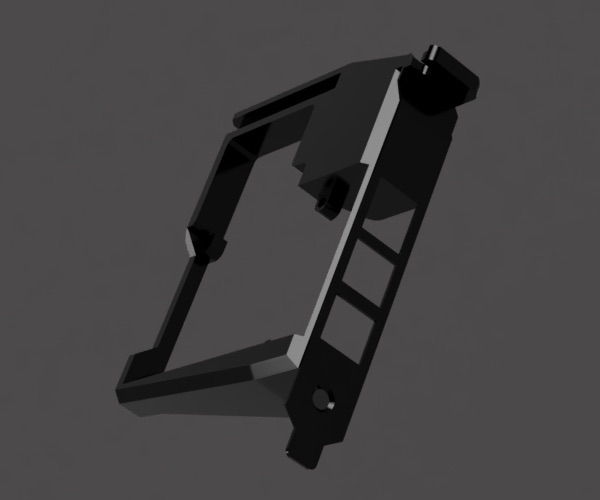
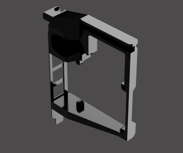
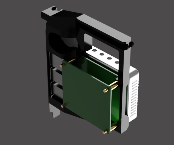
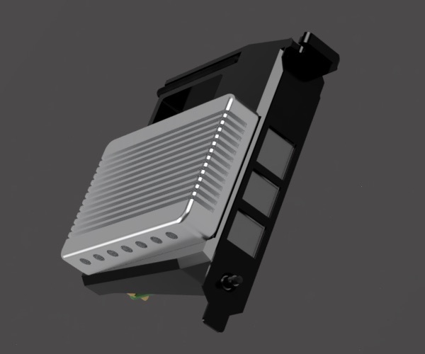
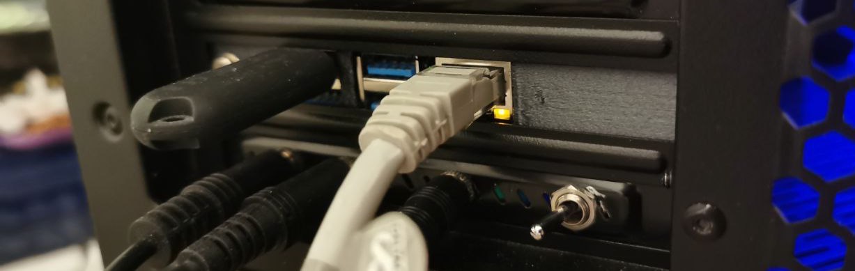
<p>I mounted it inside my main PC’s case to avoid having an external case using one of the free PCI slots.</p>

<p>It will take up to 2 PCI slots to fit the board and the <a href="https://www.friendlyelec.com/index.php?route=product/product&amp;product_id=235&amp;search=m4&amp;description=true&amp;category_id=0&amp;sub_category=true">dedicated heatsink</a>.
There’s also place for the Bluetooth and Wi-Fi antennas that come with it, and for an additional RTC battery.</p>

<p>An angled usb-c connector can be used to power it up, or even the 5V pins on the IO.
More info on the right pinout to use can be found on <a href="https://wiki.friendlyelec.com/wiki/index.php/NanoPi_M4">FriendlyElec’s wiki</a>.</p>

<h2 id="shopping-list">Shopping list</h2>

<ul>
  <li>a <a href="https://www.friendlyelec.com/index.php?route=product/product&amp;product_id=234">Nanopi M4 (v1)</a></li>
  <li>a momentary button of ~6mm diameter. Something like <a href="https://www.kjell.com/se/produkter/el-verktyg/elektronik/elektromekanik/strombrytare-for-elektronik/tryckstrombrytare/strombrytare-1-pol-frantill-rod-p36011">this</a>. It can be installed and connected to IO pins for e.g. power-cycle.</li>
  <li>4x M2.5 screws</li>
</ul>

<p>Here are some final full assembly renders and the <a href="https://www.thingiverse.com/thing:5787558">STL files</a> for download.</p>

<p><img src="/assets/img/nas-pci-slots/nas-pci-slots-1.jpg" width="230" height="192" />
<img src="/assets/img/nas-pci-slots/nas-pci-slots-2.jpg" width="230" height="192" />
<img src="/assets/img/nas-pci-slots/nas-pci-slots-filled-1.jpg" width="230" height="192" />
<img src="/assets/img/nas-pci-slots/nas-pci-slots-filled-2.jpg" width="230" height="192" /></p>

<p>The <img src="/assets/img/nas-pci-slots/nas-pci-slots-a.jpg" alt="Slot and Nanopi M4, assembled and mounted" class="big-pic" /></p>

<p>All files can be found on <a href="https://www.thingiverse.com/thing:5787558">Thingiverse</a>.</p>]]></content><author><name>TheWildBramble</name></author><category term="DIY" /><category term="3d Modelling" /><category term="3d Printing" /><category term="NAS" /><category term="Development boards" /><summary type="html"><![CDATA[Mount a development board in a PC case]]></summary></entry><entry><title type="html">Arcade controller</title><link href="https://log.thewildbramble.com/arcade-controller/" rel="alternate" type="text/html" title="Arcade controller" /><published>2022-11-01T10:00:00+00:00</published><updated>2022-11-01T10:00:00+00:00</updated><id>https://log.thewildbramble.com/arcade-controller</id><content type="html" xml:base="https://log.thewildbramble.com/arcade-controller/"><![CDATA[<p>A box for Pimoroni’s Arcade Kit. I grabbed one of <a href="https://shop.pimoroni.com/products/arcade-parts-kit?variant=29420556419155">those</a> for cheap on last Pirate Days.
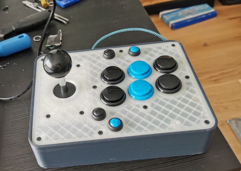
Time to build a box for it!</p>

<h2 id="shopping-list">Shopping list</h2>

<ul>
  <li>a Pimoroni <a href="https://shop.pimoroni.com/products/arcade-parts-kit?variant=29420556419155">Arcade kit</a> (or the single components)</li>
  <li>a Pimoroni <a href="https://shop.pimoroni.com/products/player-x-usb-games-controller-pcb?variant=29420561104979">Player X USB controller</a></li>
  <li>a bunch of <a href="https://www.amazon.de/-/en/gp/product/B06XCSB9N3/ref=ppx_yo_dt_b_asin_title_o02_s00?ie=UTF8&amp;psc=1">momentary buttons</a></li>
  <li>a <a href="https://shop.pimoroni.com/products/right-angle-panel-mount-extension-cables-25cm?variant=32013609631827">USB panel socket</a></li>
  <li>a bunch of (<a href="https://www.amazon.se/gp/product/B09ZHSGHXD/ref=ppx_yo_dt_b_asin_title_o05_s00?ie=UTF8&amp;psc=1">M3 thread inserts</a> and possibly a couple in <a href="https://www.amazon.se/gp/product/B088QJDPKK/ref=ppx_yo_dt_b_asin_title_o04_s00?ie=UTF8&amp;psc=1">M2.5 size</a> to fix the controller to the box)</li>
  <li>23 M3 counterscrew screws</li>
  <li>2 M2.5 flat screws (if fixing the controller to the box)</li>
  <li>4 rubber feet, diameter 6/8 mm</li>
</ul>

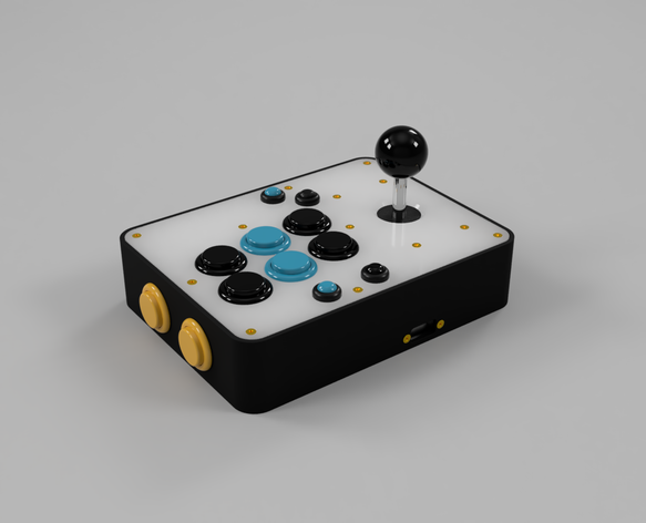
<p><img src="/assets/img/arcade-controller/arcade-controller-4.png" alt="Arcade Controller, assembled" class="big-pic" /></p>

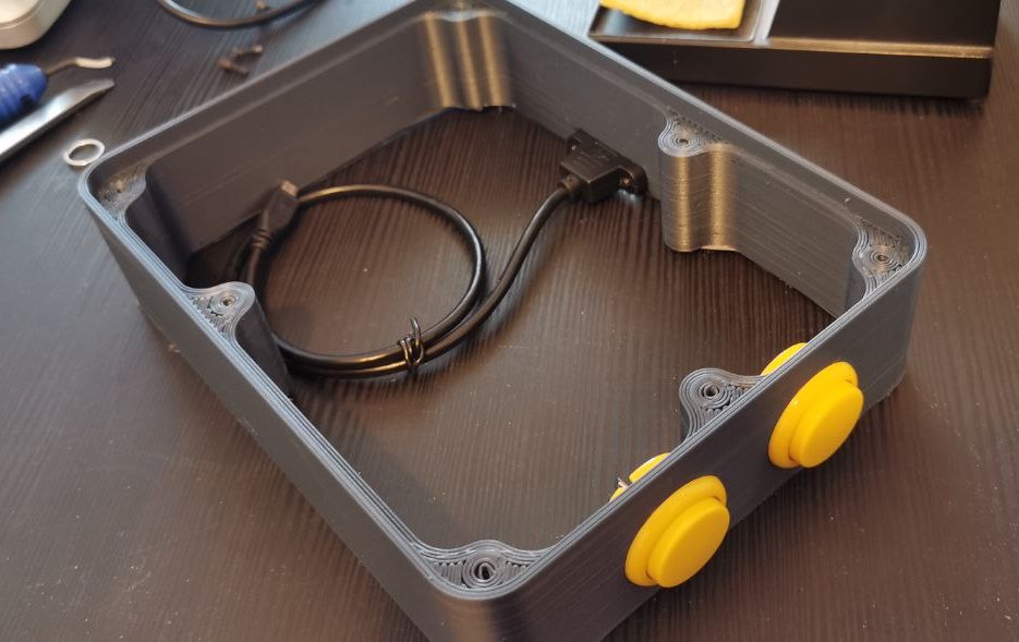
<p>I ended up drawing a box made of a top and a bottom plate and walls. It make so it’s quick to print and easy to mount, while keeping it quite robust.
I left a hole on the top side to show the controller led.</p>

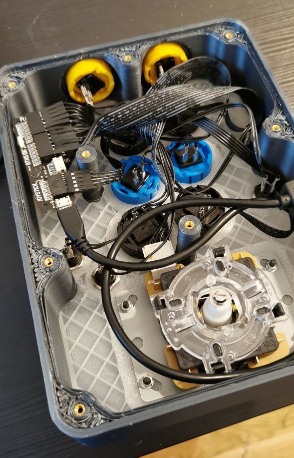
<p>Just connect all the buttons and cables, connect to a PC/Steam Link/Retroarch machine, and you’re set!</p>

<p>Here are some final assembly pics and the <a href="https://www.thingiverse.com/thing:5600579">STL files</a> for download.</p>

<p><img src="/assets/img/arcade-controller/arcade-controller-1.jpg" width="317" height="200" />
<img src="/assets/img/arcade-controller/arcade-controller-2.jpg" width="129" height="200" />
<img src="/assets/img/arcade-controller/arcade-controller-3.jpg" width="280" height="200" /></p>]]></content><author><name>TheWildBramble</name></author><category term="DIY" /><category term="3d Modelling" /><category term="3d Printing" /><category term="Pimoroni" /><summary type="html"><![CDATA[Building a simple benchtop power supply.]]></summary></entry><entry><title type="html">A simple benchtop power supply</title><link href="https://log.thewildbramble.com/a-simple-benchtop-power-supply/" rel="alternate" type="text/html" title="A simple benchtop power supply" /><published>2022-09-04T10:00:00+00:00</published><updated>2022-09-04T10:00:00+00:00</updated><id>https://log.thewildbramble.com/a-simple-benchtop-power-supply</id><content type="html" xml:base="https://log.thewildbramble.com/a-simple-benchtop-power-supply/"><![CDATA[<p>This project goes back at least to the beginning of 2022, when I figured I would need some way to power my breadboards in a slightly more clever way than hot-jumping from USB cables (and god forbid I ever need to power up something at 3.3V :grin:).</p>

<p>By that time I’d been also looking for a weekend soldering project so it was a perfect match… until I realized that it’s not the early 90s anymore and there’s no DIY kits around.</p>

<p>However, there are quite a few homemade small power supplies around <sup id="fnref:1"><a href="#fn:1" class="footnote" rel="footnote" role="doc-noteref">1</a></sup> using no more than a <strong>variable buck converter</strong> and a <strong>cheap digital volt/ampere meter</strong>.</p>

<p>I needed only a few more parts and a case.</p>

<h2 id="requirements--shopping-list">Requirements &amp; Shopping list</h2>

<ul>
  <li>no external power supply</li>
  <li>output in a range of voltages from ~1.5V to ~20V, with finer adjustments if possible</li>
  <li>monitor the current consumption</li>
  <li>it should has a reasonably small footprint</li>
</ul>

<p>What I needed then:</p>

<ul>
  <li>a <strong>buck converter</strong>. Any like <a href="https://www.amazon.se/gp/product/B09LHG43VZ/ref=ppx_yo_dt_b_asin_title_o02_s00?ie=UTF8&amp;psc=1">this</a> will work. I picked one with:
    <ul>
      <li>voltage control regulation (it should be some sort of visible trimmer in the picture. I’m going to replace it with an external potentiometer later)</li>
      <li>a voltage range from 1.5V to 30V</li>
    </ul>
  </li>
  <li>a <strong>power supply</strong> with AC/DC conversion. I chose a <a href="https://www.meanwell-web.com/en-gb/ac-dc-single-output-enclosed-power-supply-output-rs--15--24">Mean Well RS-15-24</a> which are usually compact and reliable. With its 24V output, it matches the converter’s input voltage. It’s output tolerance actually would allow you to reach almost ~30V which give room not to damage the converter at the end of its scale</li>
  <li>a small <strong>AC plug</strong></li>
  <li>a <strong>on/off switch</strong></li>
  <li>a <strong>digital voltmeter/ammeter with a screen</strong>, something like <a href="https://www.amazon.se/gp/product/B08Z3T17N9/ref=ppx_yo_dt_b_asin_title_o04_s00?ie=UTF8&amp;psc=1">this</a><sup id="fnref:2"><a href="#fn:2" class="footnote" rel="footnote" role="doc-noteref">2</a></sup></li>
  <li>a couple of fine tune <strong><a href="https://www.joom.com/sv/products/5e7d728428fc7101012bd2fb">potentiometers</a></strong>. They should match the same variable resistor of the buck converter</li>
  <li>some <strong>output plugs</strong>. I picked a couple of <a href="https://www.amazon.se/gp/product/B09GXZLC9B/ref=ppx_yo_dt_b_asin_title_o05_s00?ie=UTF8&amp;psc=1">banana plugs</a></li>
  <li>a <strong>case</strong> (more on this later)</li>
</ul>

<h3 id="planning-for-a-prototype">Planning for a prototype</h3>
<p>After I ordered the parts, the amount of free time took a bit of a turn for the worst. Project went standy-by for a few months. Not before I had time to sketch some prototype though. Here’s how it looked:</p>

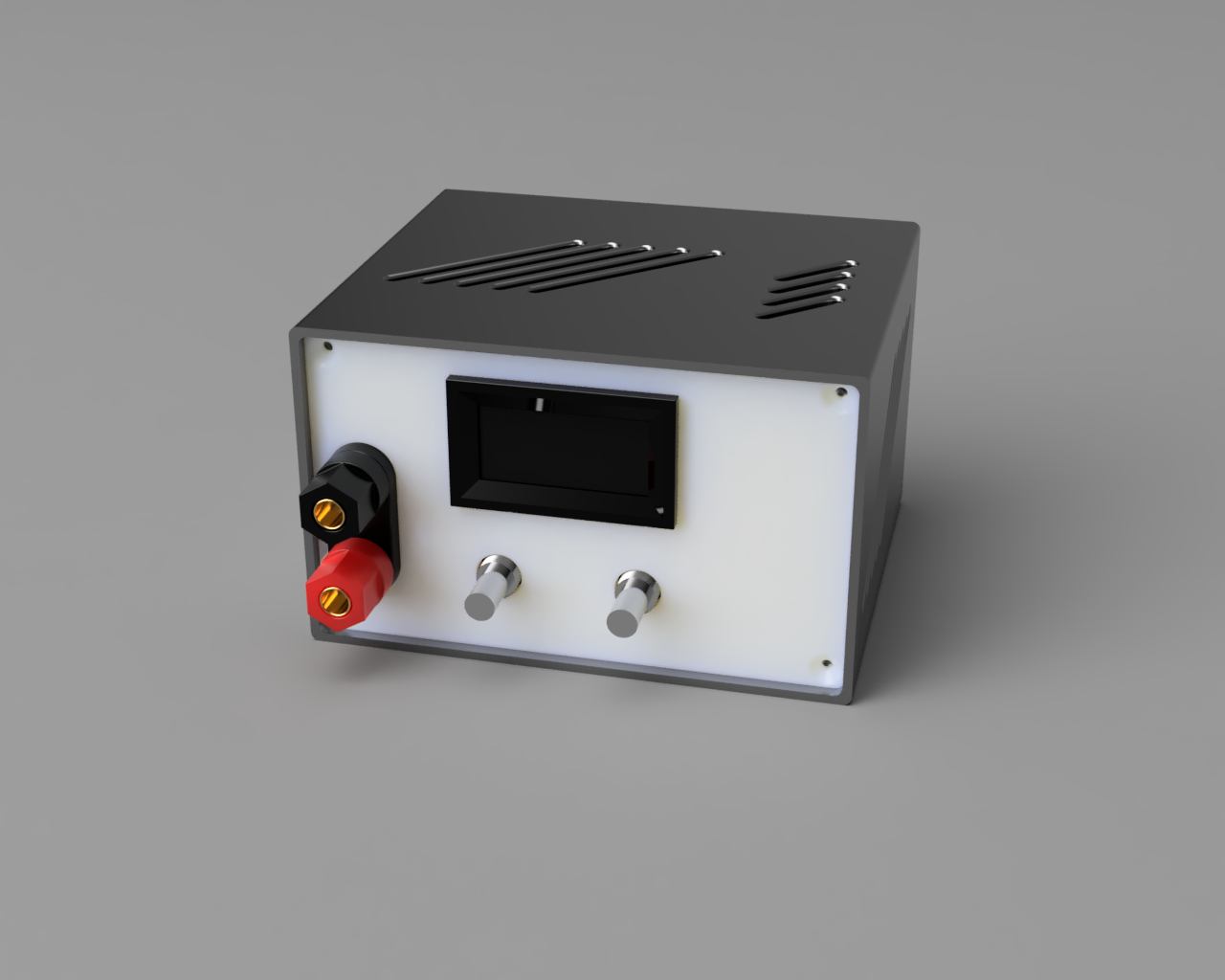
<p><img src="/assets/img/table-power-supply/table-power-supply-early-render.png" width="320" height="256" class="big-pic" /></p>

<p>Neat, right? I went as far as 3d print the outer shell.</p>
<p>But let’s jump ahead a few months, time for planning some wiring!</p>

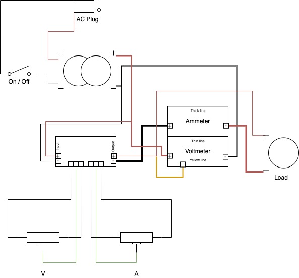
<p>The ‘wiring’ suggested from the shop page of the voltmeter is quite puzzling. But it works in the end, so given that and the other components I got, here’s the final version:</p>

<p><img src="/assets/img/table-power-supply/table-power-supply-wiring.jpg" alt="Wiring for the tabletop power supply" /></p>

<p>Yeah, I know, I should have used a better tool for this, but I’m lazy and building this should have taken an hour of so.</p>

<h3 id="building-it">Building it!</h3>

<p>So far, I never had a chance of trying it out all together, so I went now for a sample tryout.
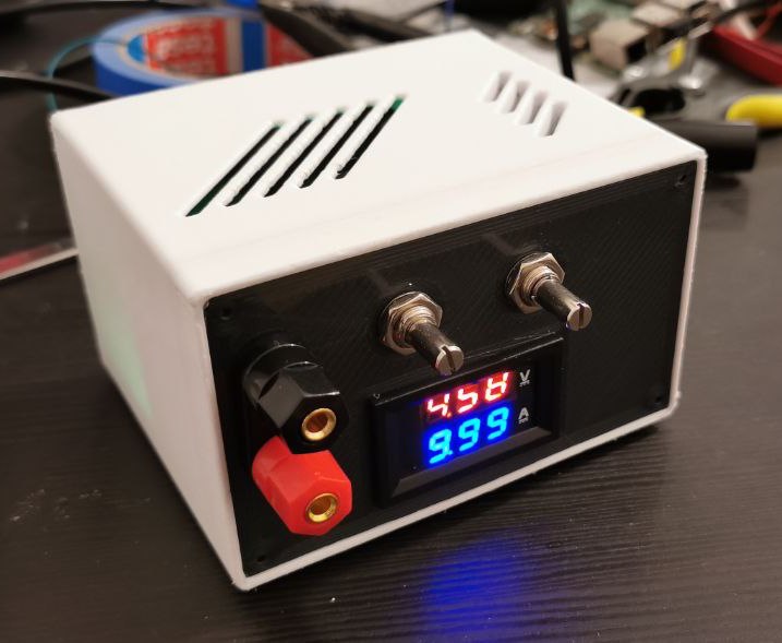
Here’s an assembled first try:</p>

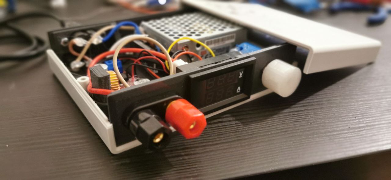
<p><img src="/assets/img/table-power-supply/table-power-supply-4.jpg" width="320" height="263" class="big-pic" /></p>

<p>It does look ok, it does fit the box, though all the pots are not yet connected.</p>

<p>A few issues presented during the process, though.</p>

<h4 id="feature-or-bug">Feature or bug?</h4>
<p>The ammeter is not really working. It seems to be a common defect of those units, either faulty or the wrong component is soldered in place. I decided I don’t really care about it since I’ll seldom have to measure that.
In the process, after a few failed current measures, I realized both the fuses of my multimeter were broken. Time to replace them!</p>

<h4 id="tune-the-voltmeter">Tune the voltmeter</h4>
<p>Two small onboard trimmer pots allow adjustment of the digital voltmeter’s displayed values. I proceed to tune them now to the same value I can measure with my multimeter on the output terminals. Same could be done for the current value.</p>

<h4 id="printed-estate">Printed estate</h4>
<p>There’s not enough space inside the printed box to handle and properly work on the components. They have to be assembled beforehand and then pushed into the box. Not ideal.
Also, I looked at my early printed case and I thought: ok, it is indeed looking pretty ugly.</p>

<p>As I was looking for a replacement for the fuse I missed in my voltmeter, I noticed that the store had a <em>ready-made enclosure</em> that surprisingly <em>fit all components perfectly</em>. 
And except for actually <em>looking better</em> than mine, it is also smaller profile and allows me to have a neater layout where I can actually mount the components easily.</p>

<p>The panels that came with the box are nice but pretty thin. I decided to re-print the front and back panels myself, so all components can fit perfectly.</p>

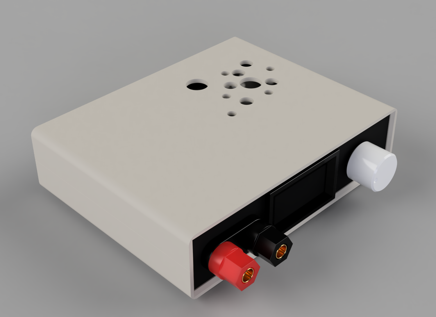
<p>So I sketched a last minute version…</p>

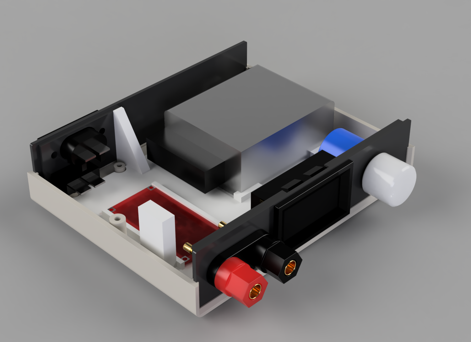
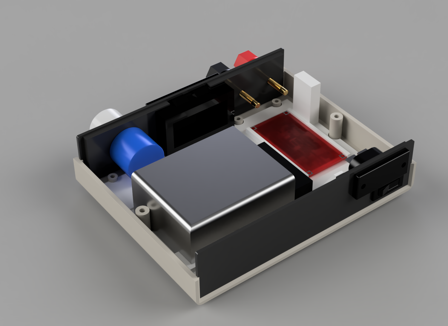
<p><img src="/assets/img/table-power-supply/last-prototype-renders/table-power-supply-3.png" width="250" height="182" />
<img src="/assets/img/table-power-supply/last-prototype-renders/table-power-supply-5.png" width="250" height="182" />
<img src="/assets/img/table-power-supply/last-prototype-renders/table-power-supply-2.png" width="250" height="182" /></p>

<p>I also dropped one of the pots, as I figured I will most likely never have a proper use for current regulation.</p>

<h4 id="final-assembly">Final assembly</h4>

<p>For the final build, I then proceeded as follows:</p>
<ul>
  <li>print the new panels</li>
  <li>cut all required cables to size</li>
  <li>cut some cute ventilation holes on the box (as per render)</li>
  <li>unsolder the variable resistor from the buck converter, and solder the panel one to it</li>
  <li>assembly all together</li>
  <li>secure all in place</li>
  <li>final test and tune of the voltmeter</li>
</ul>

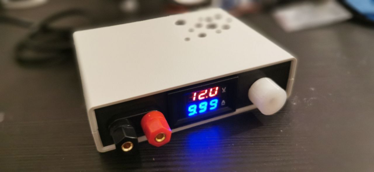
<p>Final version assembled:</p>

<p><img src="/assets/img/table-power-supply/table-power-supply-7.jpg" alt="Tabletop power supply, final version" class="big-pic" /></p>

<p><img src="/assets/img/table-power-supply/table-power-supply-6.jpg" alt="Tabletop power supply, final version, assembled" class="big-pic" /></p>

<h3 id="final-notes">Final notes</h3>

<ul>
  <li>while tuning, I realized it wasn’t easy to keep it consistent across all the range. I tuned it for around the 3.3-5V range, while it goes consistently off of a couple of decimal positions at the lower (1.5V) and higher (15V) ends</li>
  <li>current measurement is not working :cry:</li>
  <li>I had to read up again about ammeter and voltmeter positioning to validate the wiring<sup id="fnref:3"><a href="#fn:3" class="footnote" rel="footnote" role="doc-noteref">3</a></sup>. TL;DR: A voltmeter is placed in parallel with the voltage source, an ammeter is placed in series to get the full current flowing.</li>
</ul>

<h3 id="reference--notes">Reference &amp; Notes</h3>
<div class="footnotes" role="doc-endnotes">
  <ol>
    <li id="fn:1">
      <p>check out Thingiverse for DIY <a href="https://www.thingiverse.com/search?q=lab+bench+power+supply&amp;page=1&amp;type=things&amp;sort=relevant">bench lab power supplies</a>. Ok, there were actually some <em>fancy</em> ones like <a href="https://hackaday.com/2021/07/18/its-super-easy-to-build-yourself-a-usb-c-variable-power-supply-these-days/">this one</a> drawing power from the usb-c bus, which looked quite interesting, but it was even too much for my use case. <a href="#fnref:1" class="reversefootnote" role="doc-backlink">&#8617;</a></p>
    </li>
    <li id="fn:2">
      <p>note there’s plenty of versions of this component, so wiring and specs may change. Make sure to choose one that matches the input of the other two components. <a href="#fnref:2" class="reversefootnote" role="doc-backlink">&#8617;</a></p>
    </li>
    <li id="fn:3">
      <p><a href="https://www.google.com/search?q=ammeter+voltmeter+position&amp;oq=ammeter+voltmeter+position">Voltmeter &amp; Ammeter Position</a> <a href="#fnref:3" class="reversefootnote" role="doc-backlink">&#8617;</a></p>
    </li>
  </ol>
</div>]]></content><author><name>TheWildBramble</name></author><category term="DIY" /><category term="Workshop" /><category term="Electronics" /><category term="3d Modelling" /><summary type="html"><![CDATA[Building a simple benchtop power supply.]]></summary></entry></feed>