A simple benchtop power supply
This project goes back at least to the beginning of 2022, when I figured I would need some way to power my breadboards in a slightly more clever way than hot-jumping from USB cables (and god forbid I ever need to power up something at 3.3V ![]() ).
).
By that time I’d been also looking for a weekend soldering project so it was a perfect match… until I realized that it’s not the early 90s anymore and there’s no DIY kits around.
However, there are quite a few homemade small power supplies around 1 using no more than a variable buck converter and a cheap digital volt/ampere meter.
I needed only a few more parts and a case.
Requirements & Shopping list
- no external power supply
- output in a range of voltages from ~1.5V to ~20V, with finer adjustments if possible
- monitor the current consumption
- it should has a reasonably small footprint
What I needed then:
- a buck converter. Any like this will work. I picked one with:
- voltage control regulation (it should be some sort of visible trimmer in the picture. I’m going to replace it with an external potentiometer later)
- a voltage range from 1.5V to 30V
- a power supply with AC/DC conversion. I chose a Mean Well RS-15-24 which are usually compact and reliable. With its 24V output, it matches the converter’s input voltage. It’s output tolerance actually would allow you to reach almost ~30V which give room not to damage the converter at the end of its scale
- a small AC plug
- a on/off switch
- a digital voltmeter/ammeter with a screen, something like this2
- a couple of fine tune potentiometers. They should match the same variable resistor of the buck converter
- some output plugs. I picked a couple of banana plugs
- a case (more on this later)
Planning for a prototype
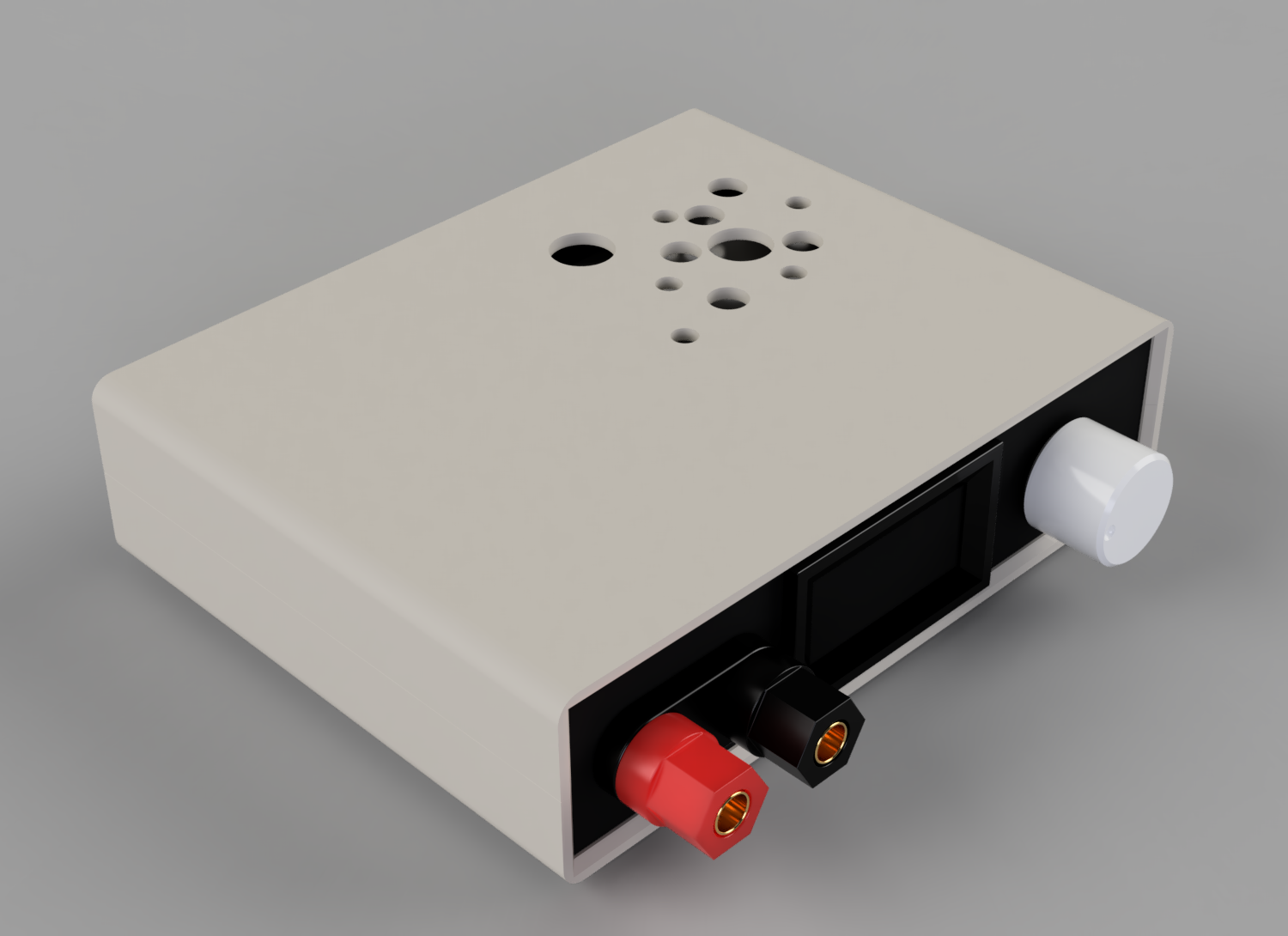
After I ordered the parts, the amount of free time took a bit of a turn for the worst. Project went standy-by for a few months. Not before I had time to sketch some prototype though. Here’s how it looked:
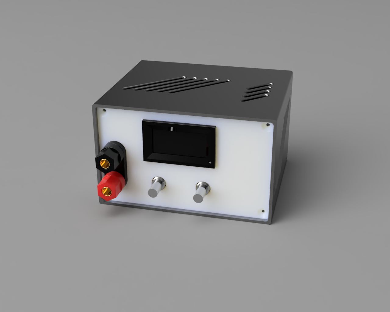
Neat, right? I went as far as 3d print the outer shell.
But let’s jump ahead a few months, time for planning some wiring!
The ‘wiring’ suggested from the shop page of the voltmeter is quite puzzling. But it works in the end, so given that and the other components I got, here’s the final version:
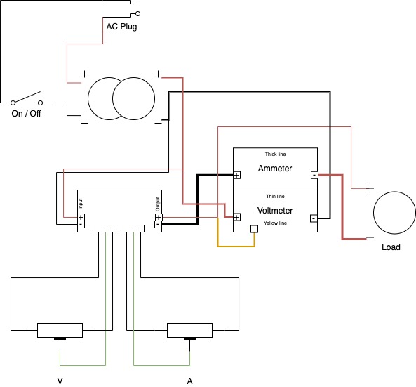
Yeah, I know, I should have used a better tool for this, but I’m lazy and building this should have taken an hour of so.
Building it!
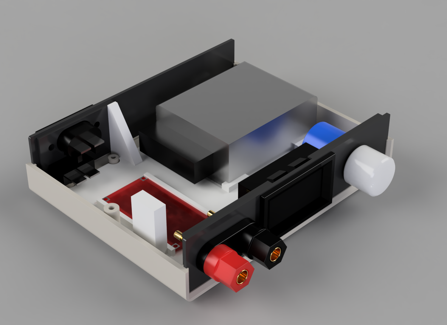
So far, I never had a chance of trying it out all together, so I went now for a sample tryout. Here’s an assembled first try:
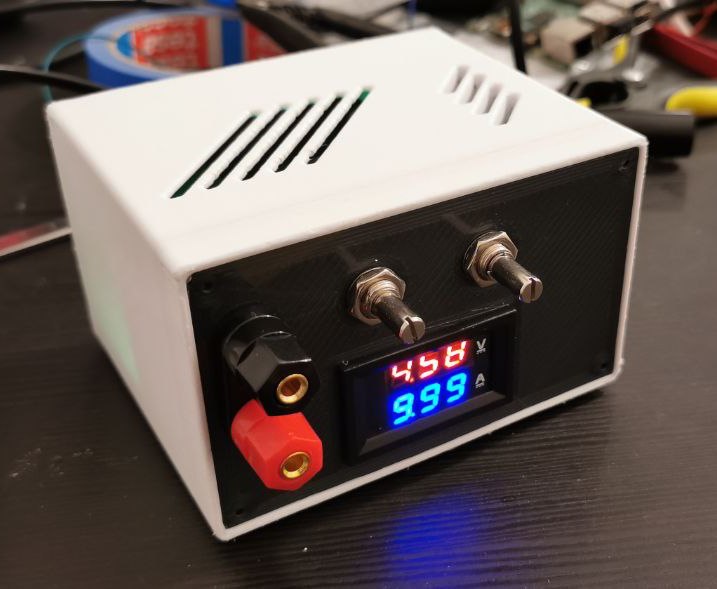
It does look ok, it does fit the box, though all the pots are not yet connected.
A few issues presented during the process, though.
Feature or bug?
The ammeter is not really working. It seems to be a common defect of those units, either faulty or the wrong component is soldered in place. I decided I don’t really care about it since I’ll seldom have to measure that. In the process, after a few failed current measures, I realized both the fuses of my multimeter were broken. Time to replace them!
Tune the voltmeter
Two small onboard trimmer pots allow adjustment of the digital voltmeter’s displayed values. I proceed to tune them now to the same value I can measure with my multimeter on the output terminals. Same could be done for the current value.
Printed estate
There’s not enough space inside the printed box to handle and properly work on the components. They have to be assembled beforehand and then pushed into the box. Not ideal. Also, I looked at my early printed case and I thought: ok, it is indeed looking pretty ugly.
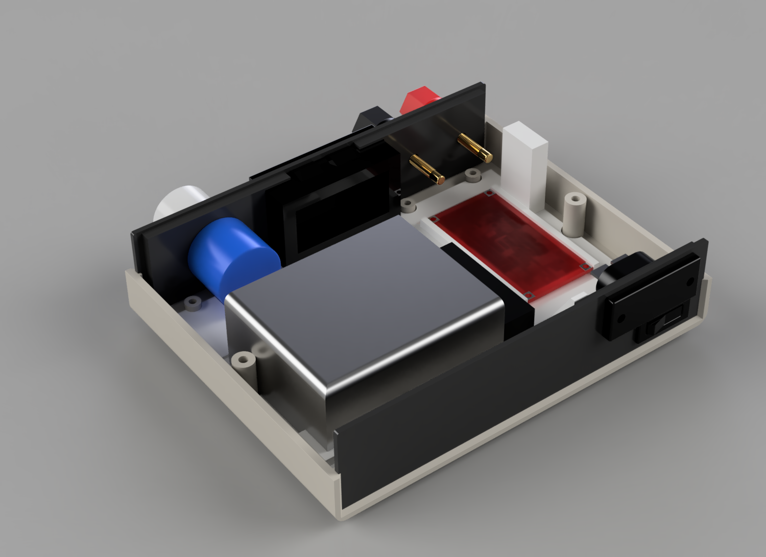
As I was looking for a replacement for the fuse I missed in my voltmeter, I noticed that the store had a ready-made enclosure that surprisingly fit all components perfectly. And except for actually looking better than mine, it is also smaller profile and allows me to have a neater layout where I can actually mount the components easily.
The panels that came with the box are nice but pretty thin. I decided to re-print the front and back panels myself, so all components can fit perfectly.
So I sketched a last minute version…
I also dropped one of the pots, as I figured I will most likely never have a proper use for current regulation.
Final assembly
For the final build, I then proceeded as follows:
- print the new panels
- cut all required cables to size
- cut some cute ventilation holes on the box (as per render)
- unsolder the variable resistor from the buck converter, and solder the panel one to it
- assembly all together
- secure all in place
- final test and tune of the voltmeter
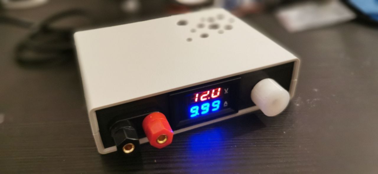
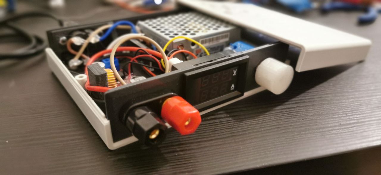
Final version assembled:
Final notes
- while tuning, I realized it wasn’t easy to keep it consistent across all the range. I tuned it for around the 3.3-5V range, while it goes consistently off of a couple of decimal positions at the lower (1.5V) and higher (15V) ends
- current measurement is not working

- I had to read up again about ammeter and voltmeter positioning to validate the wiring3. TL;DR: A voltmeter is placed in parallel with the voltage source, an ammeter is placed in series to get the full current flowing.
Reference & Notes
-
check out Thingiverse for DIY bench lab power supplies. Ok, there were actually some fancy ones like this one drawing power from the usb-c bus, which looked quite interesting, but it was even too much for my use case. ↩
-
note there’s plenty of versions of this component, so wiring and specs may change. Make sure to choose one that matches the input of the other two components. ↩